Capturing panoramic or semi-panoramic 3D scenes

Active Publication Date: 2014-04-17
FRAUNHOFER GESELLSCHAFT ZUR FOERDERUNG DER ANGEWANDTEN FORSCHUNG EV
View PDF5 Cites 129 Cited by
  • Summary
  • Abstract
  • Description
  • Claims
  • Application Information

AI Technical Summary

Benefits of technology

[0024]A basic idea underlying the present invention is that the provision of high quality panoramic or semi-panoramic 3D scenes may be achieved at reasonable efforts if the plurality of camera pairs, each of which is associated with a respective one of mirror plane surfaces of a pyramid or clipped-pyramid shaped mirror in that same is directed towards the respective associated mirror plane surface, is arranged such that for each camera pair the virtual positions of pivot points of the cameras of the respective camera pair are offset from each other along a straight baseline which, in turn, is offset from the axis of the mirror pyramid or clipped-pyramid, and a distance between virtual points of a left-hand channel camera of a first camera pair associated with a first mirror plane surface and a right-hand channel camera of a second camera pair associated with a second mirror plane surface positioned neighboring the first mirror plane surface (namely, the right of the first mirror plane surface), may be equal to the length of the common stereo baseline of the camera pairs and, more generally, deviates from a length of the baselines of the camera pairs by less than 10% of the mean length of the baselines, such as, for example, owing to mechanical tolerances. To be more precise, the inventors of the present invention found out that the aforementioned fundamental conflict between the two competing requirements imposed by the stitching of the partial scenes of neighboring camera pairs on the one hand, and the creation of enough stereo impression by use of sufficient parallax on the other hand, may be solved or at least alleviated when the baselines of the camera pairs are not only offset from the center axis of the mirror in order to allow for an overlap between neighboring fields of view of neighboring camera pairs, but when these baseline offset

Problems solved by technology

Being lost in niche markets like theme parks for a long time, these applications are now migrating into new market segments like event and exhibition technology, training centers or even entertainment.
Apart from multi-projection, a further main challenge of panoramic imaging is to create live footage supporting these special video formats in combination with ultra-high resolution.
Although the concept of omni-directional cameras for capturing 2D video panoramas is well understood and a lot of efficient systems are already available, capturing of 3D video panoramas is still a challenge and a partly unsolved problem.
For video, however, this approach is impractical due to the need of using multiple cameras on one hand and the physical dimensions of each camera on the other hand.
However, the existence of a non-zero parallax angle does not allow seamless stitching in case of close objects in the overlap area (see FIG. 1E).
Although this initial and optimal state allows a parallax-free stitching for scenes with a depth range from zer

Method used


Image

  • Capturing panoramic or semi-panoramic 3D scenes
  • Capturing panoramic or semi-panoramic 3D scenes
  • Capturing panoramic or semi-panoramic 3D scenes

Examples


Example

[0045]Whenever the same reference signs occur in the Figures, the explanation of the elements indicated using these reference signs presented with respect to one Fig. shall equally apply to the other figures where the same reference sign occurs, except for deviations explicitly mentioned.

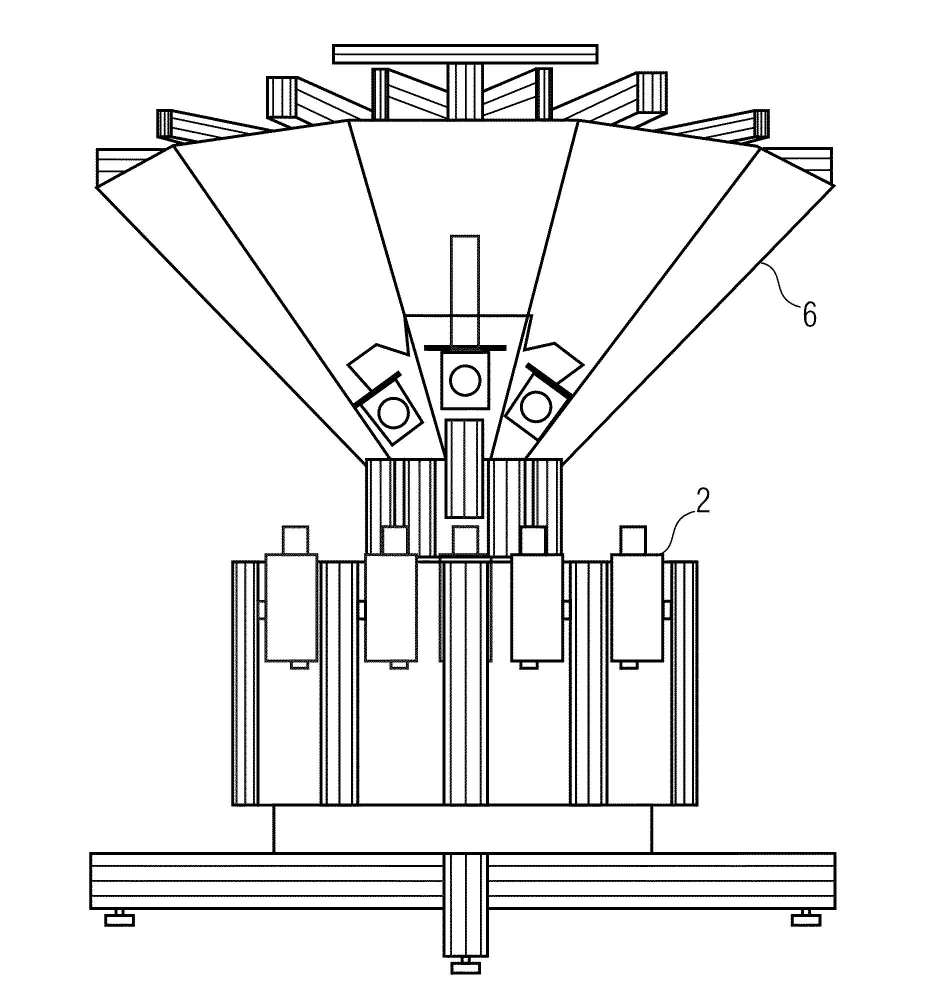
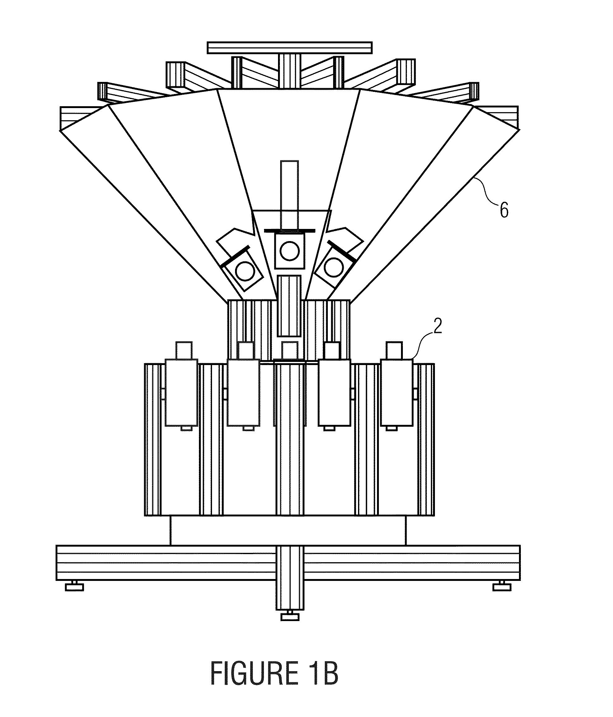
[0046]FIGS. 6A, 6B, 6C, and 6D show an apparatus for capturing panoramic or semi-panoramic 3D scenes. The apparatus comprises a mirror 10 the surface of which is rotationally symmetric about an axis 12 and is a combination of tilted mirror plane surfaces 10a, 10b and 10c (segments), the normal vectors 13 of which each intersects the axis 12 and has the same angle β relative to a plane perpendicular to axis 12. In other words, the overall mirror surface of mirror 10 resulting from the combination of mirror plane surfaces 10a, 10b and 10c results in a pyramid or a clipped pyramid having a polygonal base which may be, but is not necessarily, regular.

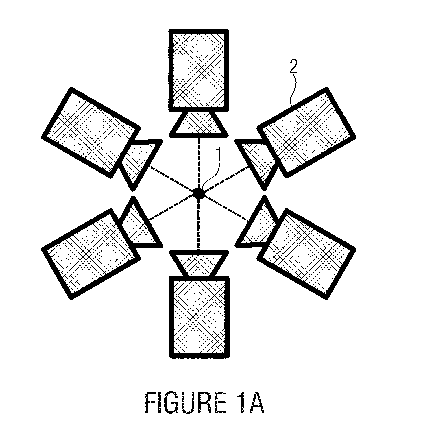
[0047]Further, the apparatus comprises a plurality of...


PUM


Abstract

A provision of high quality panoramic or semi-panoramic 3D scenes is achieved at reasonable efforts by arranging the plurality of camera pairs, each of which is associated with a respective one of mirror plane surfaces of a pyramid or clipped-pyramid shaped mirror in that same is directed towards the respective associated mirror plane surface, such that for each camera pair the virtual positions of pivot points of the cameras of the respective camera pair are offset from each other along a straight baseline which, in turn, is offset from the axis of the mirror, and a distance between virtual points of a left-hand channel camera of a first camera pair associated with a first mirror plane surface and a right-hand channel camera of a second camera pair associated with a second mirror plane surface positioned neighboring the first mirror plane surface, deviates from a length of the baselines of the camera pairs by less than 10% of the length of the baselines.

Description

CROSS-REFERENCE TO RELATED APPLICATIONS[0001]This application is a continuation of copending International Application No. PCT / EP2012 / 050190, filed Jan. 6, 2012, which is incorporated herein by reference in its entirety, and additionally claims priority from U.S. Provisional Application No. 61 / 473,595, filed Apr. 8, 2011, which is also incorporated herein by reference in its entirety.BACKGROUND OF THE INVENTION[0002]The present application relates to panoramic or semi-panoramic 3D scenes and their capturing.[0003]It is widely accepted that concept of immersive media is one of the most promising market segments of future technology. One feature of immersive media is panoramic imaging using large cylindrically or spherically curved screens, often in combination with multi-projection systems providing ultra-high resolution by exact juxtaposition and blending of multiple projector images[1][2][3][4][5]. Being lost in niche markets like theme parks for a long time, these applications are...

Claims


Application Information

Patent Timeline
IPC IPC(8): H04N5/232
CPCH04N5/23238G02B13/06G02B27/1066G02B27/143H04N5/2628G06T3/0062G03B35/08G03B37/04H04N13/243H04N23/698H04N23/90
Inventor KAUFF, PETEREISERT, PETERSCHUESSLER, JOACHIMWEISSIG, CHRISTIANFINN, ARNE
Owner FRAUNHOFER GESELLSCHAFT ZUR FOERDERUNG DER ANGEWANDTEN FORSCHUNG EV
Why Eureka
Try Eureka