Table anchored scoliosis de-rotation system and method

a scoliosis and anchored technology, applied in the field of scoliosis de-rotation system and method, can solve the problems of patient suffering from the consequences of such mis-rotation, surgeons being thwarted in properly placing pedicle screws and properly attaching, and prior art spinal fusion hardware and procedures, including those in synthes' uss, have not adequately dealt with such vertebral mis-rotation problems

Inactive Publication Date: 2014-04-17
ROVNER ROBERT A
View PDF23 Cites 21 Cited by
  • Summary
  • Abstract
  • Description
  • Claims
  • Application Information

AI Technical Summary

Benefits of technology

[0025]Another object of the present invention is to provide a system for de-rotating a spine which allows for attach...

Problems solved by technology

Such a vertebra can be either in a proper position but only in an undesirable rotation or can be both in an improper position and rotated to an improper orientation.
Prior art spinal fusion hardware and procedures, including those in Synthes' USS, have not adequately dealt with such vertebral mis-rotation.
Thus leaving the patient to suffer from the consequences of such mis-rotation.
Furthermore, when a vertebra is mis-rotated into an imp...

Method used


Image

  • Table anchored scoliosis de-rotation system and method
  • Table anchored scoliosis de-rotation system and method
  • Table anchored scoliosis de-rotation system and method

Examples


Embodiment Construction

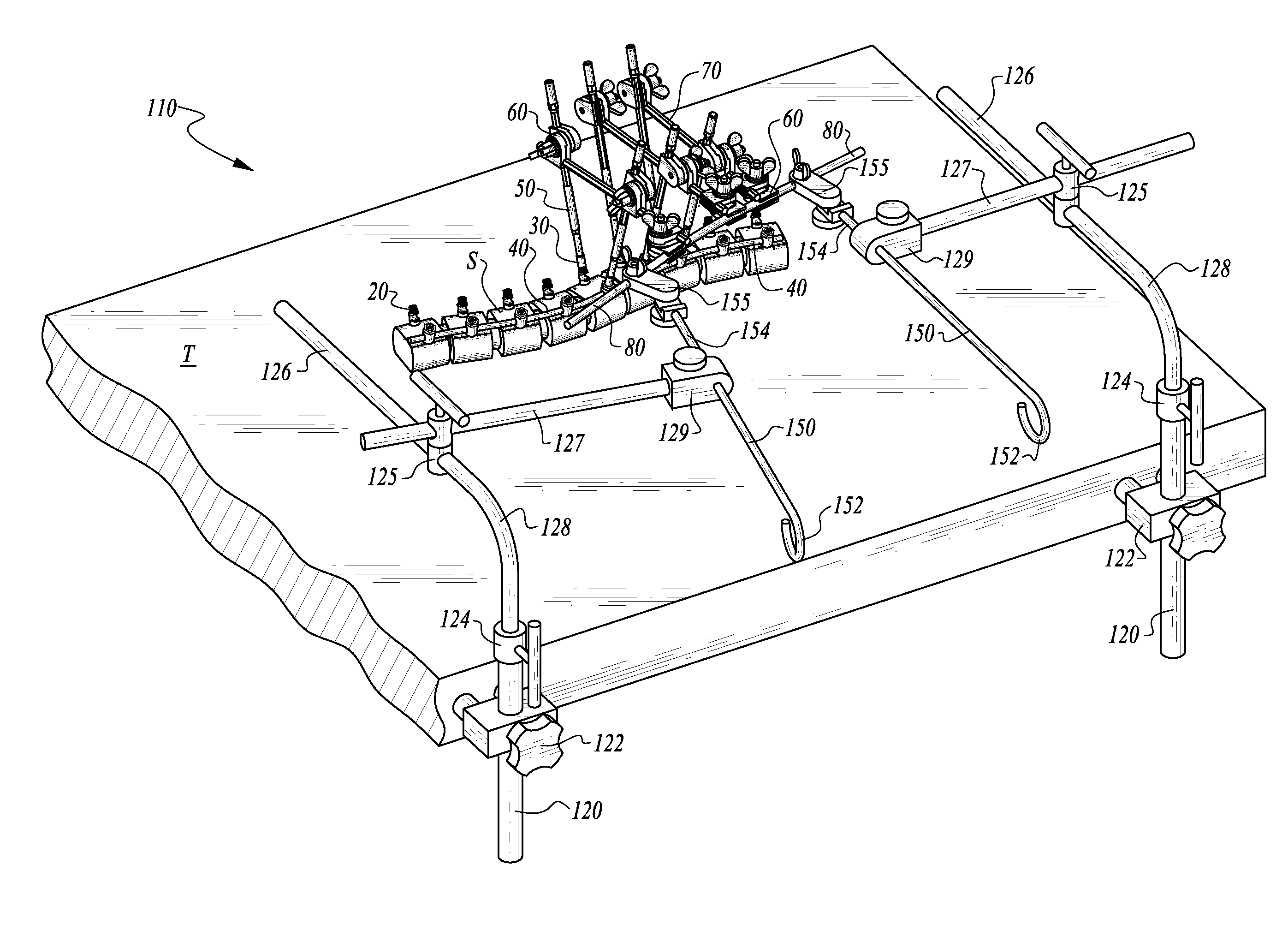
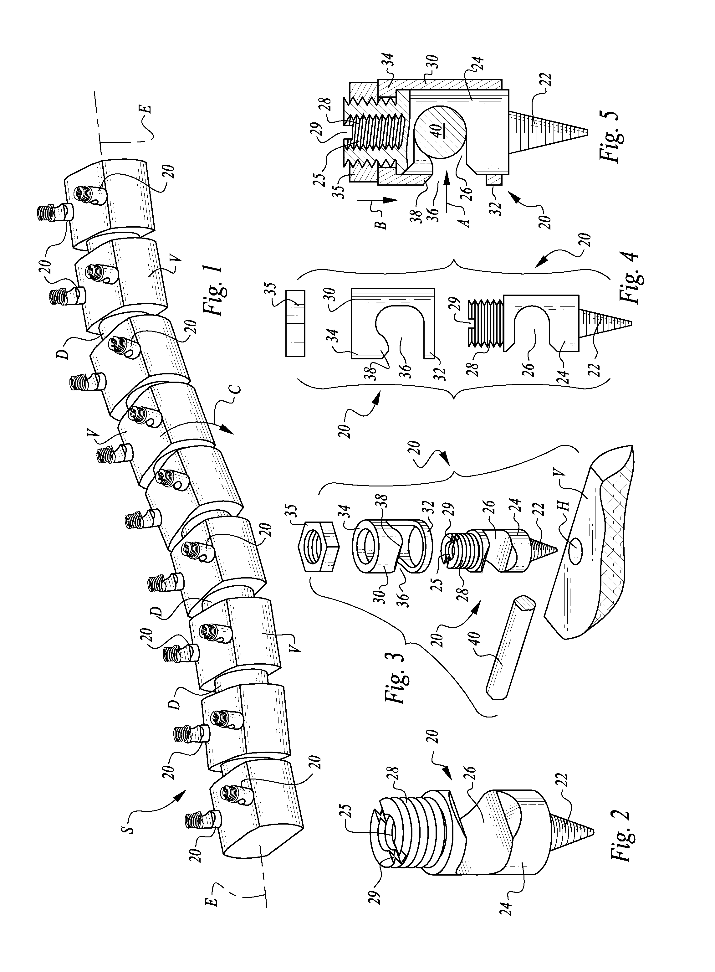
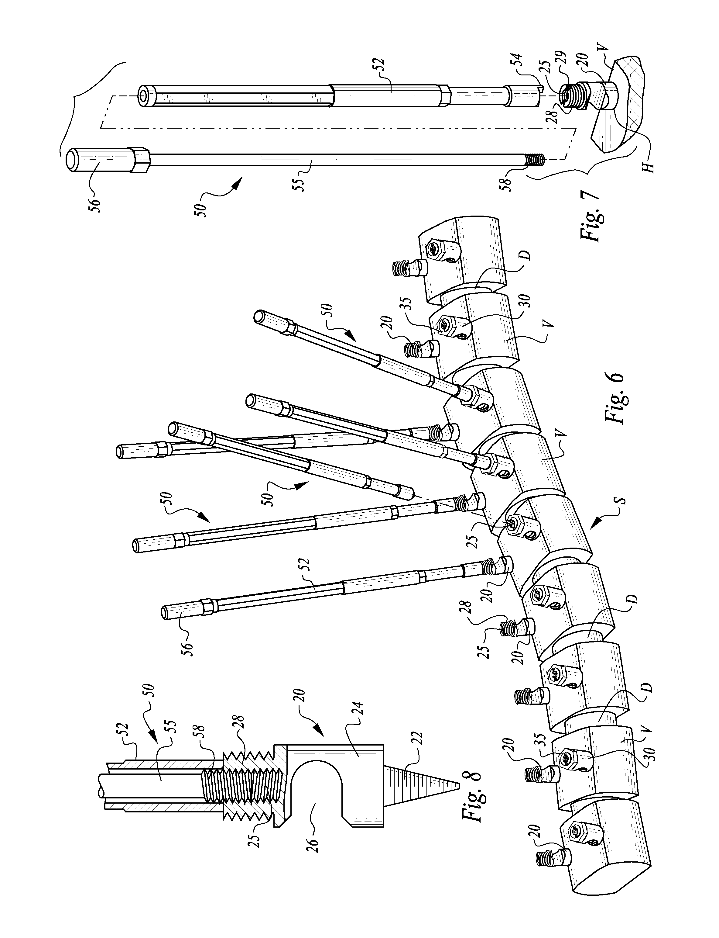
[0046]Referring to the drawings, wherein like reference numerals represent like parts throughout the various drawing figures, reference numeral 10 (FIG. 14) is directed to a system for de-rotation of a vertebra V within a spine S, where the vertebra V has been mis-rotated, such as exhibited along with a scoliosis condition. The system 10 operates upon a spine S including multiple vertebrae V spaced apart by disks D. The system 10 is useful according to a method depicted in steps from FIGS. 1, 6, 9, 11, 14 and 16 in sequence to de-rotate a vertebra V that has been mis-rotated about the elongate central axis E of the spine S. The de-rotation method can be accomplished as part of an overall spinal fusion procedure where a spine rod 40 secures the vertebrae V in a desired position through pedicle screws 20, or this de-rotation method can accompany some other spinal procedure.

[0047]In essence, and with particular reference to FIG. 14, the basic details of the various parts of the system ...


PUM


Abstract

The system includes pedicle screws anchored to multiple vertebra, at least one of which needs to be de-rotated about a central spine axis relative to adjacent vertebrae. Elongate posts are attached to the pedicle screws and extend away from the pedicle screws. A holder, such as in the form of multiple clamps and bars and a de-rotation rod, hold the posts together after de-rotation of a mis-rotated vertebra. A coupling joint secures the posts to a table upon which a spine surgery patient is resting. With the vertebra held where desired, a spine rod can then be attached to heads of the pedicle screws to hold the vertebrae in their desired positions. After spine rod attachment, to the pedicle screws, other portions of the system can then be removed. The pedicle screws and spine rods remain implanted to hold the vertebrae in their de-rotated positions.

Description

CROSS-REFERENCE TO RELATED APPLICATIONS[0001]This application is a continuation-in-part of U.S. patent application Ser. No. 12 / 931,824, filed on Feb. 10, 2011 and issued as U.S. Pat. No. 8,608,782 on Dec. 17, 2013.FIELD OF THE INVENTION[0002]The following invention relates to methods and apparatuses for use in surgical procedures to treat structural deficiencies in the spine. More specifically, this invention relates to surgical methods and apparatuses for adjusting improper rotation of vertebra relative to a central axis of the spine, such as in cases of scoliosis where individual vertebra are undesirably mis-rotated out of a proper alignment.BACKGROUND OF THE INVENTION[0003]A primary characteristic of scoliosis is that an elongate central axis of the spine is curved rather than straight, when viewed posteriorly or anteriorly. Such cases of scoliosis can vary between minor and severe. In more severe cases, one treatment is to intervene surgically, aligning the individual vertebra o...

Claims


Application Information

Patent Timeline
IPC IPC(8): A61B17/70
CPCA61B17/7074A61B17/7002A61B17/7034A61B17/708A61B90/57A61B90/50
Inventor ROVNER, ROBERT A.
Owner ROVNER ROBERT A
Why Eureka
Try Eureka