Heat dissipation device

a heat dissipation device and heat dissipation chamber technology, applied in the direction of basic electric elements, semiconductor devices, lighting and heating apparatus, etc., can solve the problems of increasing the cost, affecting the cooling effect of the second heat source, and affecting the use of the device, so as to save the cost and space of the heat dissipation device. , the effect of increasing the air volume of the second outl

Inactive Publication Date: 2014-04-24
ASUSTEK COMPUTER INC
View PDF8 Cites 7 Cited by
  • Summary
  • Abstract
  • Description
  • Claims
  • Application Information

AI Technical Summary

Benefits of technology

[0010]Since the housing includes the first outlet and the second outlet, and the switch is disposed at the first outlet, when the impeller rotates, the switch opens or closes the first outlet, which affects the air volume of the first outlet and the second outlet. When the switch opens the first outlet, the airflow outflows from the first outlet and the second outlet, thus, the heat of the first heat source and that of the second heat source can be dissipated synchronously When the switch doses the first outlet, the airflow outflows alone the second outlet, and thus the ai

Problems solved by technology

An electronic device usually generates heat while operation, if the heat cannot dissipate out efficiently, the electronic device is easily crashed, and the electronic components of the electronic device may be even burned out, which causes property damage or injury to users.
However, two sets of cooling components not only increase the cost, but

Method used


Image

  • Heat dissipation device
  • Heat dissipation device
  • Heat dissipation device

Examples


Embodiment Construction

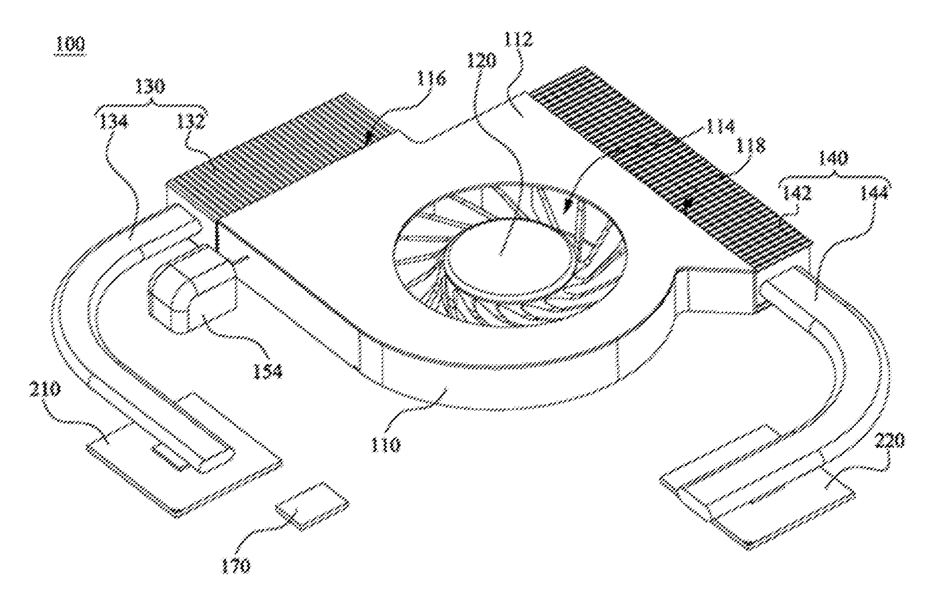
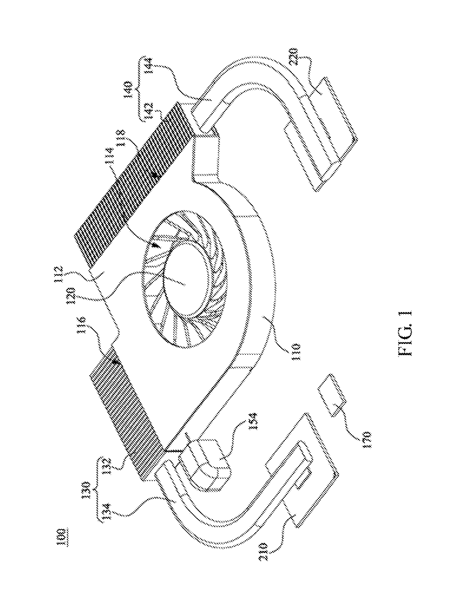
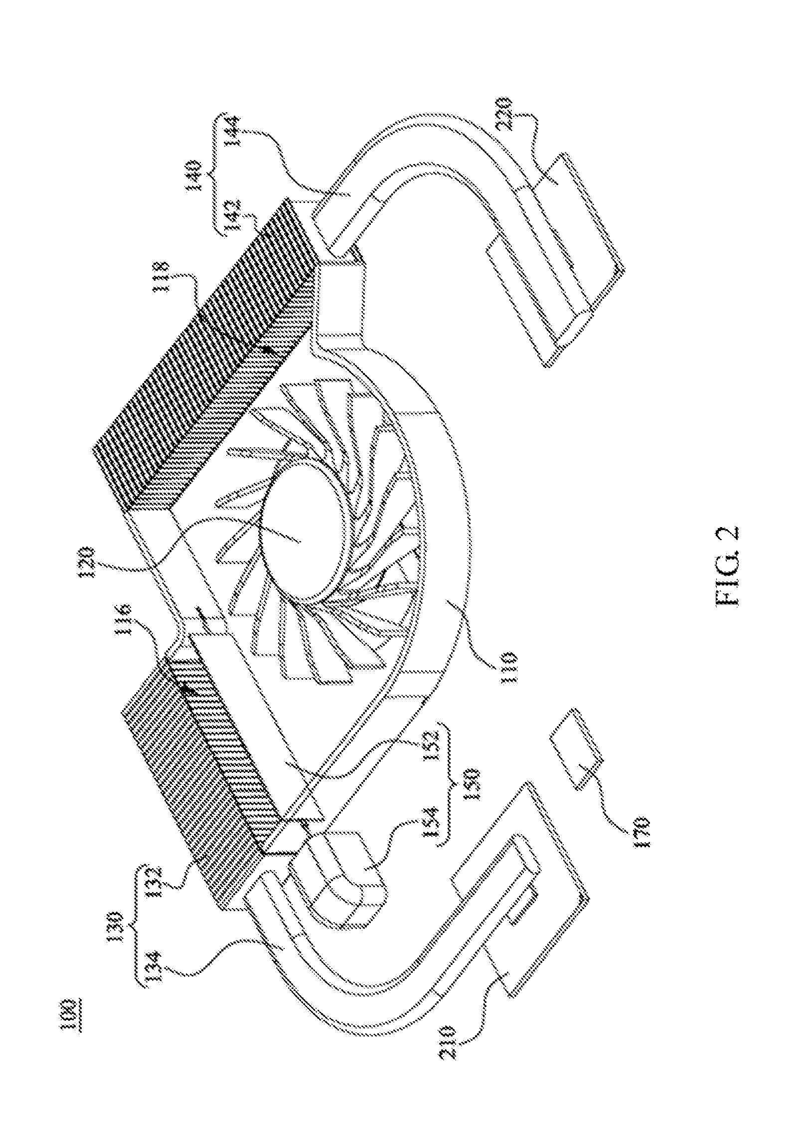
[0020]FIG. 1 is a three-dimensional schematic diagram showing a heat dissipation device in an embodiment. FIG. 2 is a three-dimensional schematic diagram showing the heat dissipation device in FIG. 1 where an upper cover of a housing is removed. Please refer to FIG. 1 and FIG. 2, the heat dissipation device 100 is applied to an electronic device with a first heat source 210 and a second heat source 220. The electronic device may be a notebook computer, a desktop computer or a tablet computer. The first heat source 210 and the second heat source 220 may be chips on a circuit board (such as a mainboard). The first heat source 210 may be graphics processing unit (GPU), and the second heat source 220 may be central processing unit (CPU), however, the types of the first heat source 210 and the second heat source 220 are not limited herein.

[0021]The heat dissipation device 100 includes a housing 110, an impeller 120, a first heat conductive assembly 130, a second heat conductive assembly ...


PUM


Abstract

A heat dissipation device is provided. The heat dissipation device is applied to an electronic device with a first heat source and a second heat source. The heat dissipation device includes a housing, an impeller, a first heat conductive assembly, a second heat conductive assembly and an switch. The housing includes an accommodating space, a first outlet and a second outlet. The first outlet and the second outlet are connected to and through the accommodating space. The impeller is disposed in the accommodating space. The first heat conductive assembly is connected to the first outlet and the first heat source. The second heat conductive assembly is connected to the second outlet and the second heat source. The switch is disposed at the first outlet to open or dose the first outlet.

Description

CROSS-REFERENCE TO RELATED APPLICATION[0001]This application claims the priority benefit of U.S. provisional application Ser. No. 61 / 716,627, filed on Oct. 22, 2012 and CN application serial No. 201310409860.6, filed on Sep. 10, 2013. The entirety of the above-mentioned patent application are hereby incorporated by reference herein and made a part of specification.BACKGROUND OF THE INVENTION[0002]1. Field of the Invention[0003]The invention relates to a heat dissipation device.[0004]2. Description of the Related Art[0005]An electronic device usually generates heat while operation, if the heat cannot dissipate out efficiently, the electronic device is easily crashed, and the electronic components of the electronic device may be even burned out, which causes property damage or injury to users.[0006]Fans, cooling fins, heat pipes and other cooling components are currently used in the electronic device for reducing the temperature of chips. For example, when a central processing unit (C...

Claims


Application Information

Patent Timeline
IPC IPC(8): F28F3/02
CPCF28F3/02F28F27/02F28D15/0275F28F2250/00H01L23/3672H01L23/427H01L23/467H01L2924/0002H01L2924/00
Inventor MA, CHEN-HSUANCHIOU, ING-JER
Owner ASUSTEK COMPUTER INC
Why Eureka
Try Eureka