
Electromagnetically-countered display systems and methods

a display system and display technology, applied in the field of electromagnetically counted display systems, can solve the problems of difficult shielding, hazardous to human health, and electromagnetic waves with varying frequencies irradiated by various devices, and achieve the effect of reducing the potential adverse effects of electromagnetic waves, facilitating acquisition, and facilitating greater distan

Inactive Publication Date: 2014-04-24
SHIM YOUNGTACK
View PDF0 Cites 7 Cited by
  • Summary
  • Abstract
  • Description
  • Claims
  • Application Information

AI Technical Summary

Benefits of technology

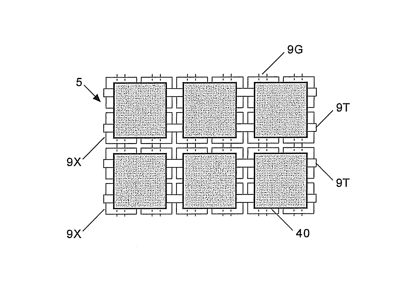
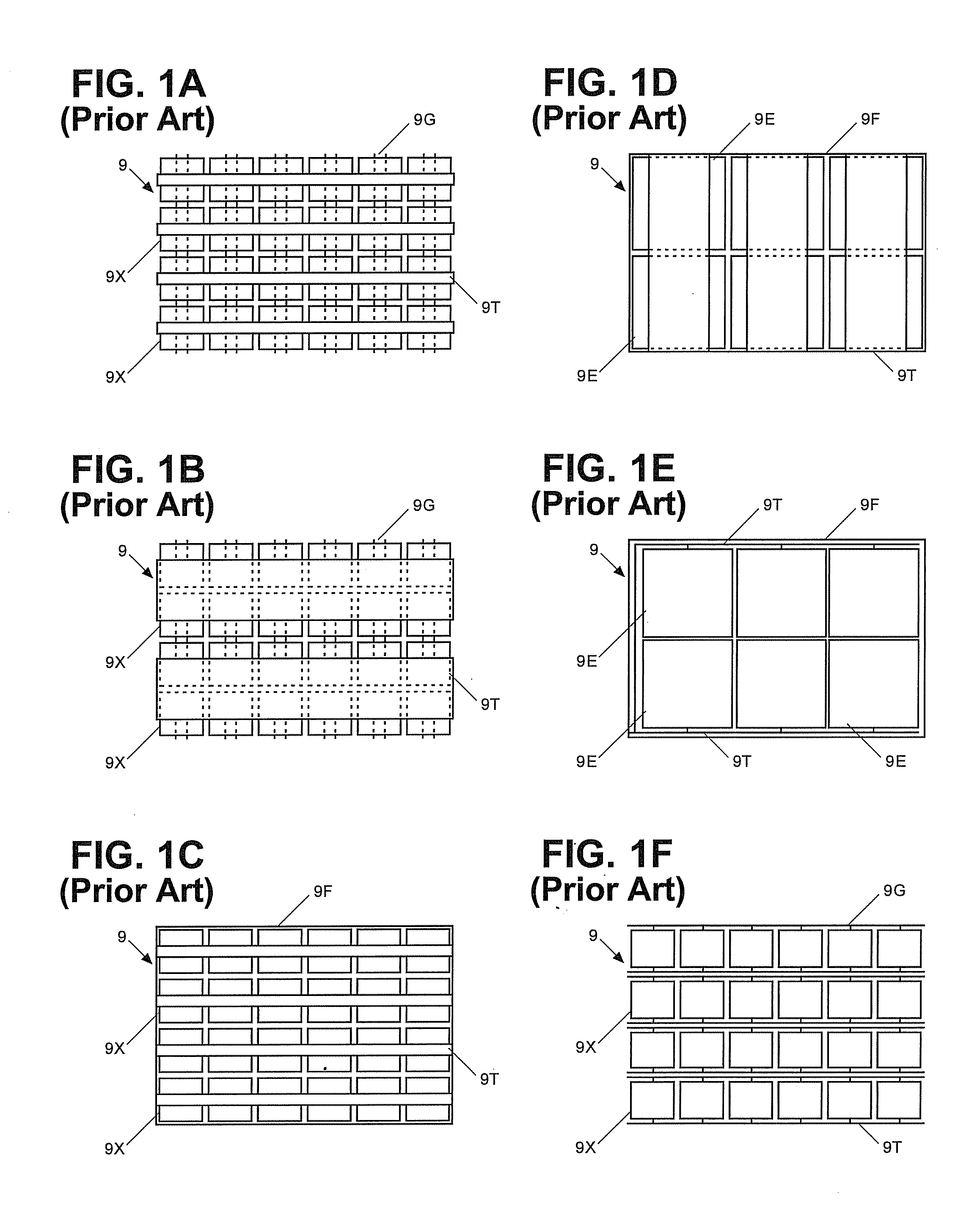
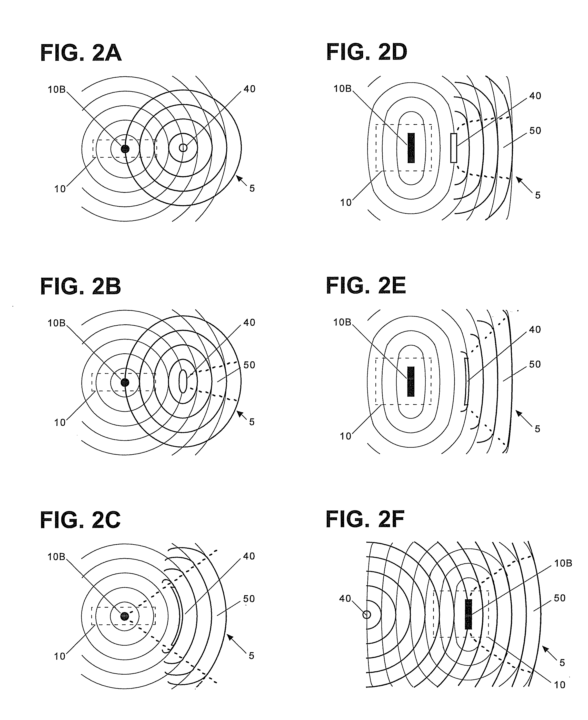
The present invention is about a system that uses counter waves to cancel out harmful electromagnetic waves generated by a base unit. The counter units can be shaped and sized to match the base unit or can be placed along the wave front of the harmful waves. The invention also includes various modes for countering one or all of the base units using a single or multiple counter units, as well as electric and magnetic shields to minimize the irradiation of harmful waves. The technical effects of the invention include reducing the harmful effects of electromagnetic waves on the environment and promoting safety for users.

Problems solved by technology

It is now well established in the scientific community that electromagnetic waves with varying frequencies irradiated by various devices may be hazardous to human health.
It cannot be too emphasized that it is very difficult to shield against magnetic waves of the 60-hertz electromagnetic waves which have wavelengths amounting to thousands of kilometers and that such 60-hertz magnetic waves are omnipresent in any corner of the current civilization.

Method used


Image

  • Electromagnetically-countered display systems and methods
  • Electromagnetically-countered display systems and methods
  • Electromagnetically-countered display systems and methods

Examples


Embodiment Construction

[0181]Reference will now be made in detail to the present embodiments of the present invention, examples of which are illustrated in the accompanying drawings, wherein like reference numerals refer to the like elements throughout. The embodiments are described below in order to explain the present invention by referring to the figures.

[0182]The present invention relates to an electromagnetically-countered display system with at least one wave source irradiating harmful electromagnetic waves and at least one counter unit for emitting counter electromagnetic waves and for countering the harmful waves by the counter waves, e.g., by canceling at least a portion of the harmful waves with the counter waves in a target space and / or by suppressing the harmful waves with such counter waves from propagating toward the target space. More particularly, the present invention relates to counter units for the electromagnetically-countered display systems and to various mechanisms for countering th...


PUM


Abstract

The present invention relates to an electromagnetically-countered display system including at least one wave source and at least one counter unit, where such a wave source irradiates harmful electromagnetic waves and the counter unit emits counter electromagnetic waves for countering the harmful waves therewith. More particularly, the present invention relates to various counter units for the electromagnetically-countered display system and to various mechanisms to counter the harmful waves with the counter units, e.g., by matching configurations of the counter units with those of the wave sources, by matching wavefronts of the harmful waves with those the counter waves, and so on. The present invention also relates to various methods of countering the harmful waves with such counter waves by source and / or wave matchings, various methods of providing the counter units for emitting the counter waves defining desired wave characteristics, and the like. The present invention further relates to various processes for providing the electromagnetically-countered display systems and their counter units. The present invention further relates to various electric and magnetic shields employed either alone or in conjunction with the counter units for minimizing irradiation of the harmful waves from the shaving system.

Description

CROSS-REFERENCE TO RELATED APPLICATIONS[0001]This application is a continuation application of U.S. patent application Ser. No. 13 / 242,059, filed on Sep. 23, 2011 entitled “Electromagnetically-countered display systems and methods”, which is a continuation-in-part application of U.S. patent application Ser. No. 12 / 985,031, filed on Jan. 5, 2011, issued to U.S. Pat. No. 8,588,437 entitled “Genetic electromagnetically-countering processes”, which is a continuation-in-part application of U.S. patent application Ser. No. 12 / 985,026, filed on Jan. 5, 2011, issued to U.S. Pat. No. 8,588,436 entitled “Generic electromagnetically-countered methods”, which is a continuation-in-part application of U.S. patent application Ser. No. 12 / 985,042, filed on Jan. 5, 2011 entitled “Electromagnetically-countered systems and methods by maxwell equations”, which is a continuation-in-part application of U.S. patent application Ser. No. 12 / 961,111, filed on Dec. 6, 2010, issued to U.S. Pat. No. 8,369,105 e...

Claims


Application Information

Patent Timeline
Patent Type & Authority Applications(United States)
IPC IPC(8): A61N1/16
CPCA61N1/16H05K9/0071H05K9/0054H05K2201/0707
Inventor SHIM, YOUNGTACK
Owner SHIM YOUNGTACK
Learn More