Display device and program

Inactive Publication Date: 2014-04-24
SEMICON ENERGY LAB CO LTD
View PDF39 Cites 27 Cited by
  • Summary
  • Abstract
  • Description
  • Claims
  • Application Information

AI Technical Summary

Benefits of technology

[0021]According to one embodiment of the present invention, eye fat

Problems solved by technology

As electronic devices including display devices have come into widespread use, it has become more often that users keep looking at display devices for a long time.
Light emitted from a display device includes short-wavelength light, which increases eye fatigue of a

Method used


Image

  • Display device and program
  • Display device and program
  • Display device and program

Examples


embodiment 1

[0040]In this embodiment, a structural example of a display device of one embodiment of the present invention and an example of a method for driving the display device are described with reference to drawings.

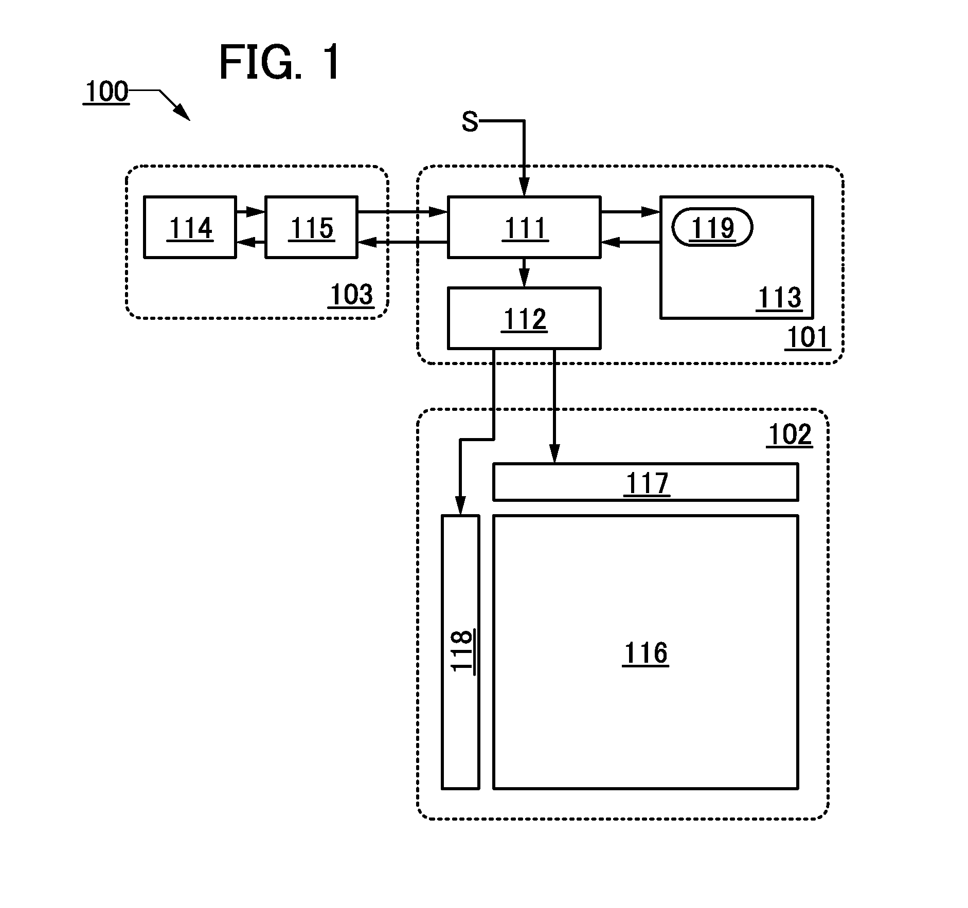
[0041]FIG. 1 is a block diagram illustrating a structural example of a display device 100 described as an example in this embodiment.

[0042]Although the block diagram attached to this specification shows components classified by their functions in independent blocks, it is difficult to classify actual components according to their functions completely and it is possible for one component to have a plurality of functions.

[0043]The display device 100 includes a control unit 101, a display unit 102, and a detection unit 103.

[0044]The control unit 101 includes an arithmetic device 111, a controller 112, and a memory device 113. The display unit 102 includes a pixel portion 116, a driver circuit 117, and a driver circuit 118. The detection unit 103 includes a detector 114 and a contr...

modification example 1

[0082]Described below is a structural example of a display device which is partly different from the display device 100 described above. Note that portions similar to those described above are not described in some cases.

[0083]A display device 150 illustrated in FIG. 4A is an example of a liquid crystal display device. The display device 150 differs from the display device 100 in that the display unit 102 includes a backlight 121 and in that the control unit 101 includes a controller 122.

[0084]The backlight 121 is preferably a backlight capable of emitting light of two or more different colors, the luminances of which can be separately controlled. Here, the backlight 121 preferably emits light of three colors, red (R), green (G), and blue (B), or more.

[0085]Alternatively, it is possible that only light of colors whose luminances are to be changed can be separately controlled. For example, the backlight 121 may emit blue (B) light and light of two colors (e.g., red (R) and green (G))...

modification example 2

[0095]Described below is another structural example of a display device which is partly different from the display device 100 described above. Note that portions similar to those described above are not described in some cases.

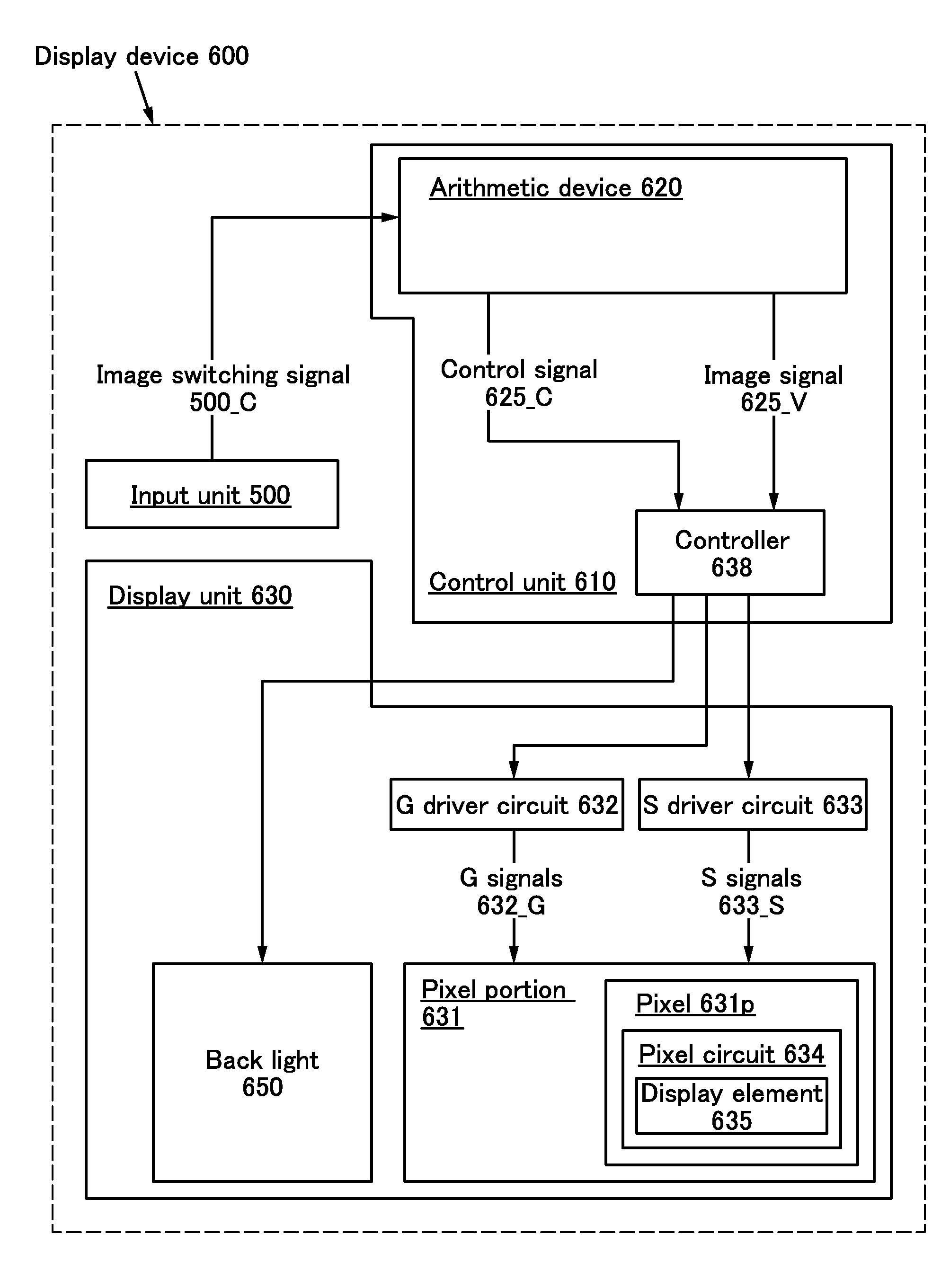
[0096]A display device 160 illustrated in FIG. 5 differs from the display device 100 in that setting information 125 is stored in the memory device 113.

[0097]The setting information 125 includes information for determining the processing which the arithmetic device 111 performs. For example, it is determined by the information whether or not to perform processing for changing, on the basis of the user's fatigue condition, the luminance of light emitted from the display unit 102. The setting information 125 may also include a parameter for setting the degree of changing luminance, specifying a color whose luminance of light is to be changed, setting the rate of detecting the fatigue condition, setting the threshold value in determining the fatigue condition, or...


PUM


Abstract

Provided are a display device and the driving method of the display device with which eye fatigue of a user in long-term use of the display device is reduced. The display device includes a display unit, a detection unit, and a control unit. The detection unit detects a condition of a user's eye to obtain detected information and transmits the detected information to the control unit. The control unit extracts fatigue information on the user from the detected information and drives the display unit such that a luminance of light with a wavelength shorter than or equal to a predetermined wavelength among light emitted from the display unit is changed on the basis of the fatigue information.

Description

BACKGROUND OF THE INVENTION[0001]1. Field of the Invention[0002]The present invention relates to a display device for displaying images and to a program for driving the display device.[0003]2. Description of the Related Art[0004]Display devices such as liquid crystal display devices are used for a television, a monitor of a personal computer (PC), a display of a laptop PC, a display of a portable information terminal, and the like.[0005]It is known that short-wavelength light is related to eye fatigue of a viewer and damage to the retina. Therefore, methods for removing short-wavelength light from light which reaches the viewer's eye have been studied. For example, Patent Document 1 discloses a lens which selectively blocks light with wavelengths between 300 nm and 549 nm.REFERENCEPatent Document[0006][Patent Document 1] U.S. Pat. No. 4,878,748SUMMARY OF THE INVENTION[0007]As electronic devices including display devices have come into widespread use, it has become more often that us...

Claims


Application Information

Patent Timeline
IPC IPC(8): G09G5/10
CPCG09G5/10G09G3/3413G09G3/3648G09G3/3666G09G5/06G09G2300/0426G09G2320/062G09G2320/0666G09G2354/00G09G2370/08
Inventor ISHITANI, TETSUJIHIRAKATA, YOSHIHARUYAMAZAKI, SHUNPEI
Owner SEMICON ENERGY LAB CO LTD
Why Eureka
Try Eureka