Method for inhibiting melting of arctic sea ice

Inactive Publication Date: 2014-04-24
NAKAISHI MASANORI
View PDF2 Cites 3 Cited by
  • Summary
  • Abstract
  • Description
  • Claims
  • Application Information

AI Technical Summary

Benefits of technology

[0011]Seawater temperatures rise the closer to the sea surface. Thus, as described above, the fence is set for blocking seawater from the sea surface down to a certain depth, thereby blocking only seawater of high temperatures which flows in the vicinity of the sea surface, making it possible to effectively prevent temperature elevation of seawater in the Arctic Ocean and also inhibit melting of Arctic sea ice. Further, since the Strait is communicatively connected, deep water tends to flow below the fence without any disturbance. Thus, it is possible to eliminate the adverse effects on the global environment due to blockage of deep water.
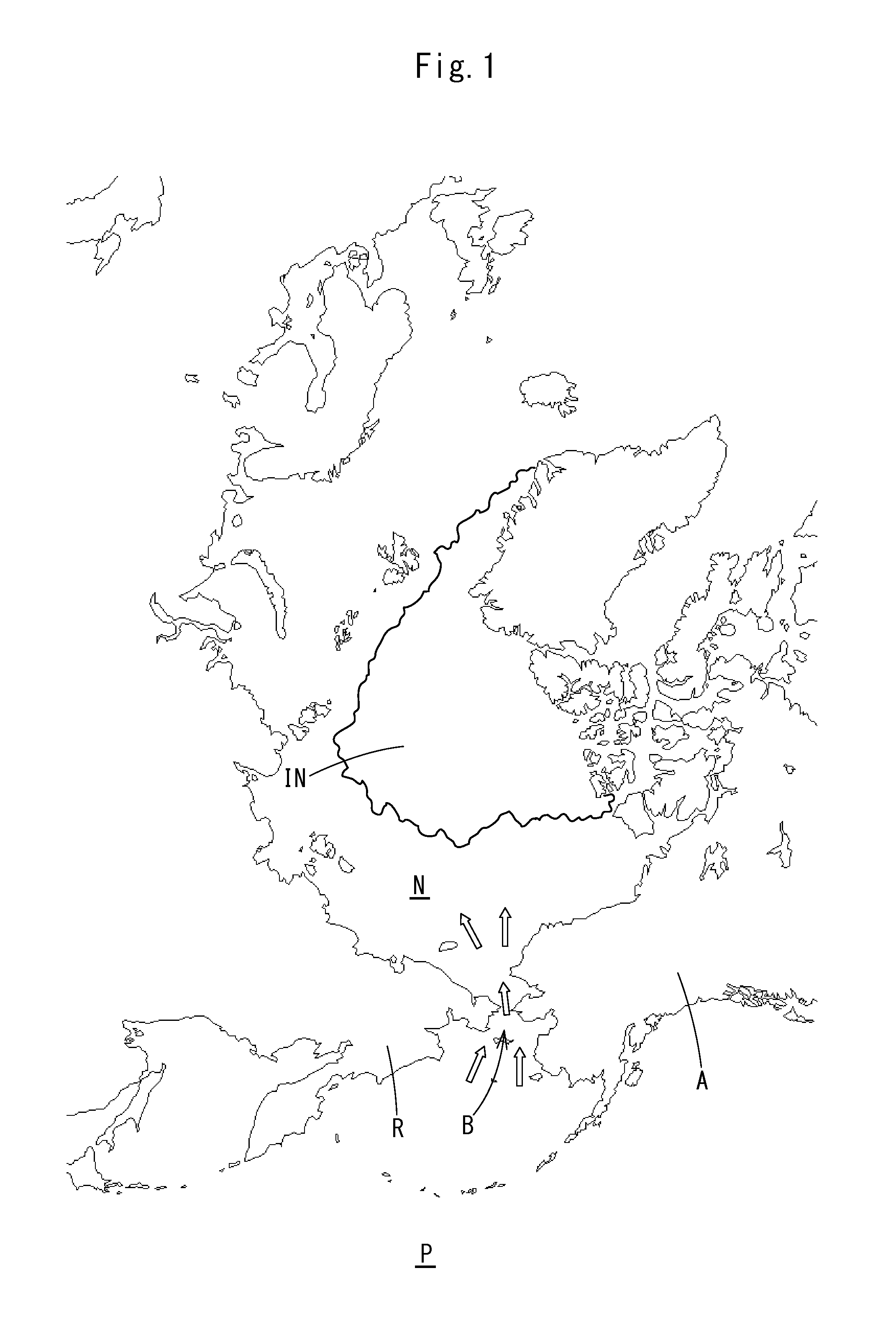
[0012]It is preferable that in the method of the present invention for inhibiting melting of Arctic sea ice, the fence is set in a region which is not closed by sea ice in the Bering Strait. In the Bering Strait, during the winter, the sea surface is closed by sea ice, and seawater in the vicinity of the sea surface is prevented from flowing from the Pacific Ocean into the Arctic Ocean. However, in the summer, sea ice in the Bering Strait is melted and even the seawater in the vicinity of the sea surface will flow from the Pacific Ocean into the Arctic Ocean. Therefore, during the summer when sea ice is melted, a fence is set in place of sea ice, thus making it possible to prevent seawater in the vicinity of the sea surface from flowing into the Arctic Ocean from the Pacific Ocean even during the summer.
[0013]It is preferable that in the method of the present invention for inhibiting melting of Arctic sea ice, the fence is set along a side face of sea ice in the Bering Strait which is on the side of the Pacific Ocean. Th

Problems solved by technology

However, blocking the Bering Strait entirely from the sea surface down to the sea bottom with dams or the like as proposed in Non-Patent Document 1 requires enormous cos

Method used


Image

  • Method for inhibiting melting of arctic sea ice
  • Method for inhibiting melting of arctic sea ice
  • Method for inhibiting melting of arctic sea ice

Examples


first embodiment

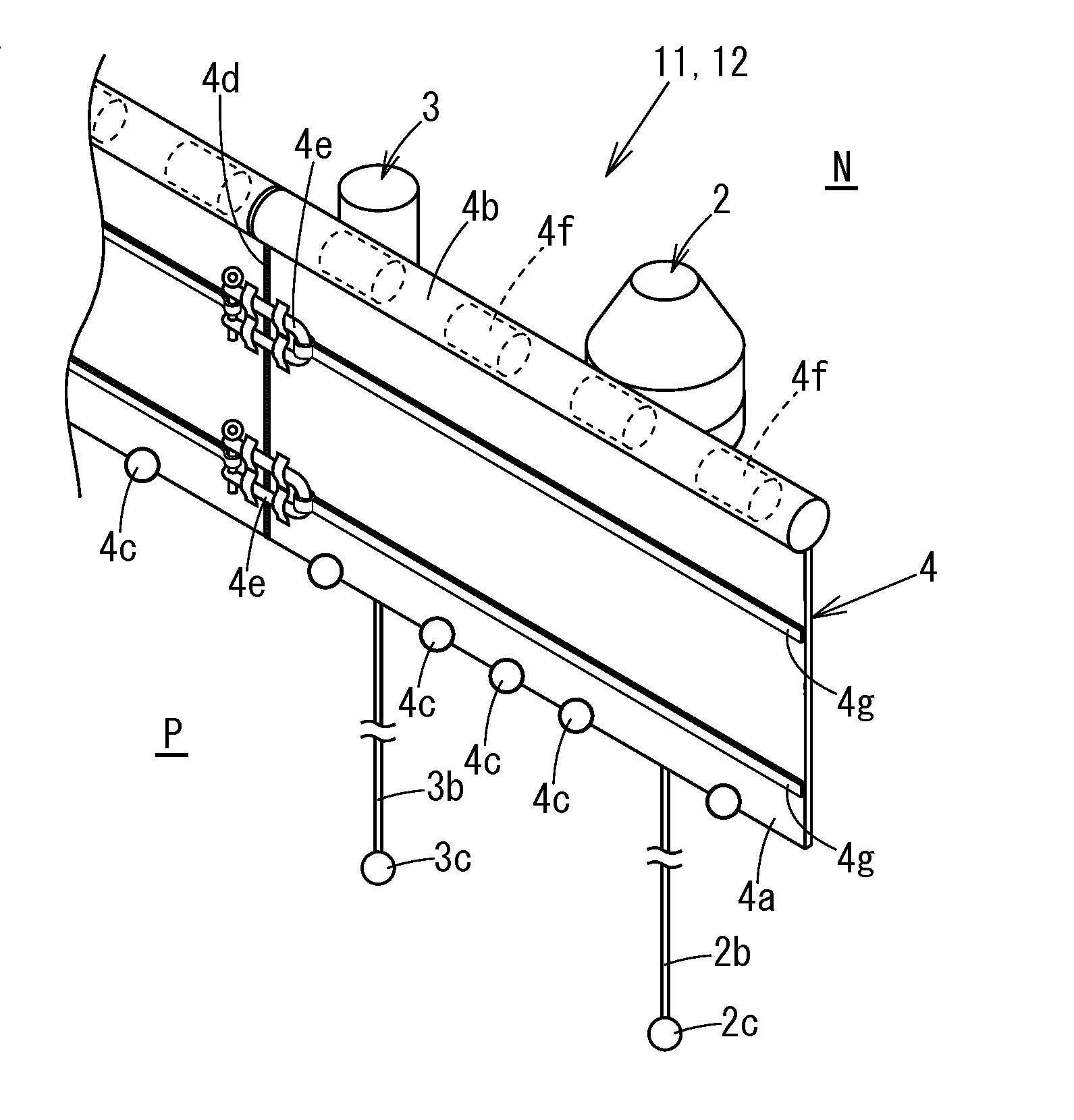
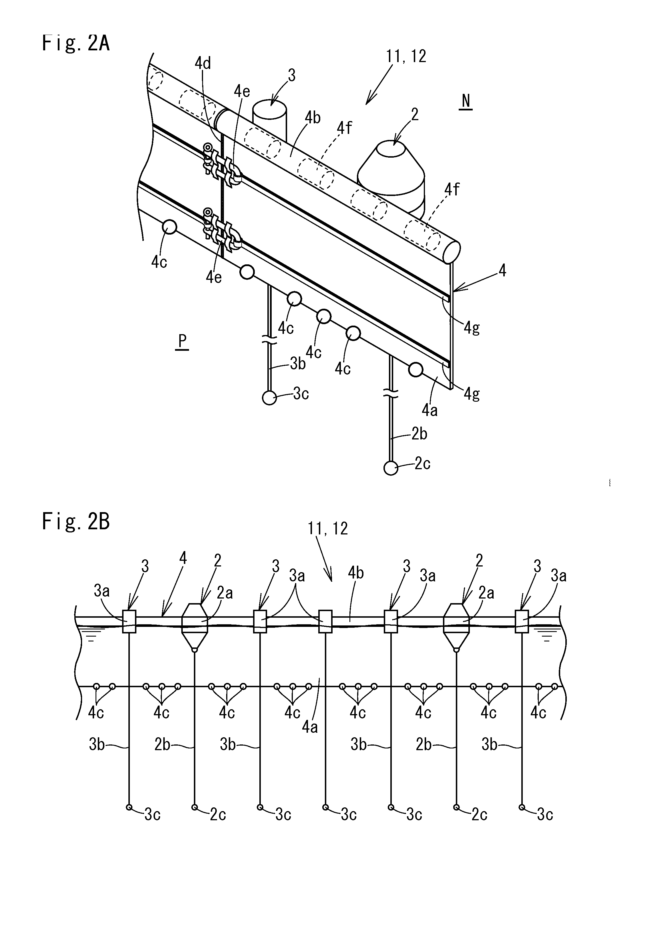
[0041]In FIG. 2A, FIG. 2B and FIG. 3, there is shown a method for inhibiting melting of Arctic sea ice according to a First Embodiment. This embodiment is carried out during the summer when sea ice IB in the Bering Strait is melted. In the illustrated example, two fences are arrayed in parallel and set. A reference numeral 11 indicates a first fence on the side of the Arctic Ocean, while a reference numeral 12 indicates a second fence on the side of the Pacific Ocean. As shown in FIG. 2A, each of the first fence 11 and the second fence 12 is provided with a large-size buoy 2, a small-size buoy 3 and a fence main body 4.

[0042]The fence main body 4 is provided with a band-shaped sheet part 4a which is, for example, 2 to 3 meters in width (“a certain depth”) and 200 meters in length, a floating body 4b including a number of columnar expanded polystyrene bodies 4f installed along an upper side of the sheet part 4a, and a fence anchor 4c attached to a lower side of the sheet part 4a. The...

second embodiment

[0048]In FIG. 4A to FIG. 8, there is shown a method for protecting Arctic sea ice IN according to a Second Embodiment. This embodiment is carried out during the winter when the Bering Strait B has been closed by sea ice IB. A reference numeral 211 indicates a first fence and a reference numeral 212 indicates a second fence. As shown in FIG. 4A, FIG. 4B and FIG. 5, each of the first fence 211 and the second fence 212 is provided with a buoy 2, a columnar support 23, a fence main body 4 and a floating wire 6. Also, in the Second Embodiment, the first fence 211 and the second fence 212 are set so as to be in parallel with each other. It is noted that in the Second Embodiment and a Third Embodiment which is to be described later, members common to those of the First Embodiment will be given the same reference numerals, with description omitted.

[0049]As shown in FIG. 6A and FIG. 6B, the floating wire 6 is formed so that a wire 6a is covered from inside with a polyvinyl chloride coating 6...

third embodiment

[0052]FIG. 9A and FIG. 9B show a method for inhibiting melting of Arctic sea ice IN according to a Third Embodiment. In the Third Embodiment as well, two fences, that is, a first fence 311 and a second fence 312 are arrayed so as to be in parallel with each other. As shown in FIG. 9A, each of the first fence 311 and the second fence 312 is provided with a large-size buoy 2, a small-size buoy 3, a fence main body 4 and a net 35. In the Third Embodiment, as shown in FIG. 9A, first, the net 35 is attached to the buoys 2, 3 arrayed in the sea. The net 35 is provided at its lower end with an anchor 35a. Thereafter, as shown in FIG. 9B, the fence main body 4 is attached to the net 35 which is on the side of the Pacific Ocean. As described above, the net 35 is installed on the fence main body 4 which is on the side of the Arctic Ocean, by which it is possible to prevent the fence 311 from drifting away by sea currents.

[0053]It is noted that the net 35 may be installed only at a site where ...


PUM


Abstract

Seawater is prevented from flowing from the Pacific Ocean into the Arctic Ocean through the Bering Strait, thereby inhibiting melting of Arctic sea ice. Fences are set for blocking seawater in the Bering Strait from the sea surface down to a certain depth, and, of seawater flowing into the Arctic Ocean from the Pacific Ocean, seawater in the vicinity of the sea surface is prevented from flowing into the Arctic Ocean by using the fences.

Description

CROSS-REFERENCE TO RELATED APPLICATIONS[0001]This application is a continuation of International Application No. PCT / JP2012 / 077324 filed on Oct. 23, 2012, the contents of which are incorporated herein by reference in their entirety.FIELD OF THE INVENTION[0002]The present invention relates to a method for artificially controlling melting of Arctic sea ice caused by seawater which flows from the Pacific Ocean into the Arctic Ocean through the Bering Strait.BACKGROUND OF THE ART[0003]In recent years, with the increasing effects of global warming, floods and droughts have occurred in various parts of the world, and inhibiting the effects of global warming has emerged as a common issue for all of humanity. Global warming is directly caused by an increase in greenhouse gases trapped in the atmosphere such as carbon dioxide. Sea ice in the Arctic Ocean, etc., and glaciers melt and decrease by global warming, which then causes a decrease in sunlight reflected by sea ice and glaciers, thereb...

Claims


Application Information

Patent Timeline
IPC IPC(8): E02B7/02
CPCE02B7/02E02B15/02E02B1/003
Inventor NAKAISHI, MASANORI
Owner NAKAISHI MASANORI
Why Eureka
Try Eureka