Device and method for cutting brittle member and cut-out brittle member

Inactive Publication Date: 2014-04-24
IHI CORP
View PDF1 Cites 54 Cited by
  • Summary
  • Abstract
  • Description
  • Claims
  • Application Information

AI Technical Summary

Benefits of technology

[0007]A splash or a mist of the cooling medium, or a waste fluid flowing on a glass plate, when intruding into a region where a laser beam passes, absorb the laser beam. Therefore it is required to regu

Problems solved by technology

This regulation increases effort in process control an

Method used


Image

  • Device and method for cutting brittle member and cut-out brittle member
  • Device and method for cutting brittle member and cut-out brittle member
  • Device and method for cutting brittle member and cut-out brittle member

Examples


Embodiment Construction

[0018]Exemplary embodiments of the present invention will be described hereinafter with reference to the appended drawings.

[0019]A device according to the present embodiment is preferably applicable to cutting of a glass plate but is of course also applicable to cutting of any other brittle member. The descriptions hereinafter exemplify a case in which a glass plate 2 is cut but the exemplified case is no more than an example and not limiting to the present invention.

[0020]Further, in the descriptions hereinafter, in general, the term “splash” means droplets having a scattering nature, and the term “mist” includes a fog and fine droplets close to a fog and means such a substance having a drifting nature.

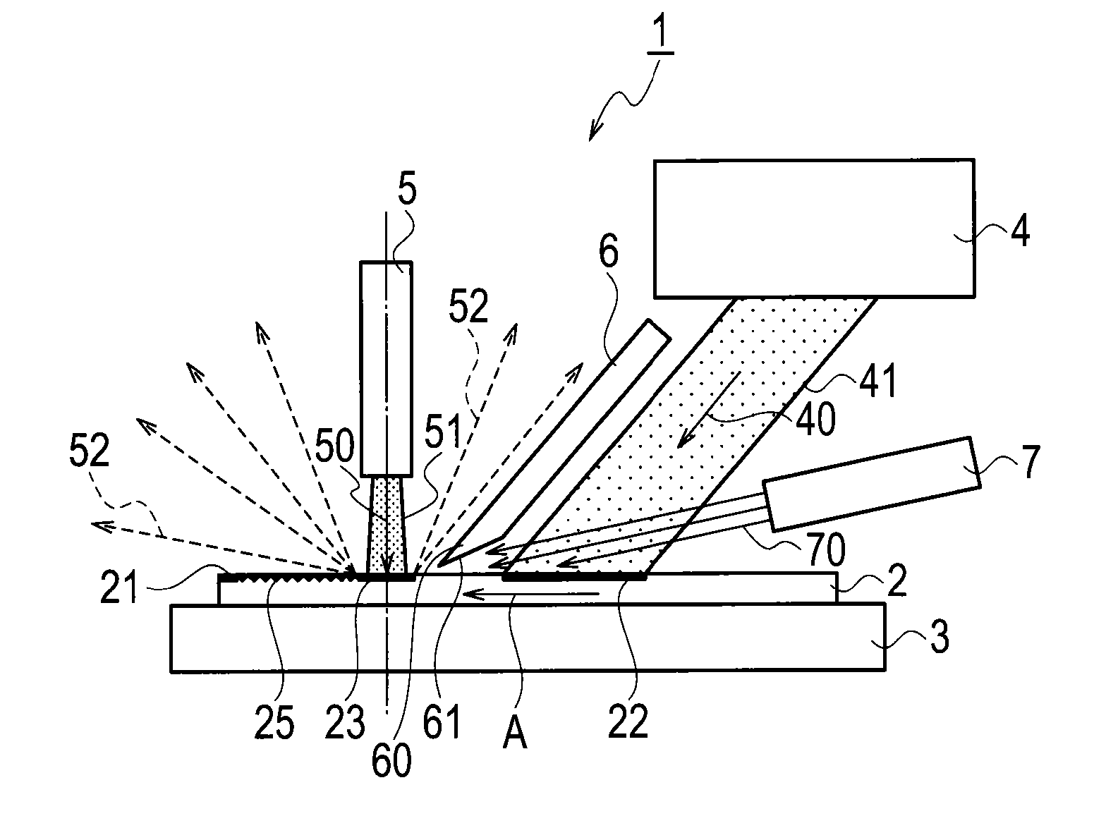
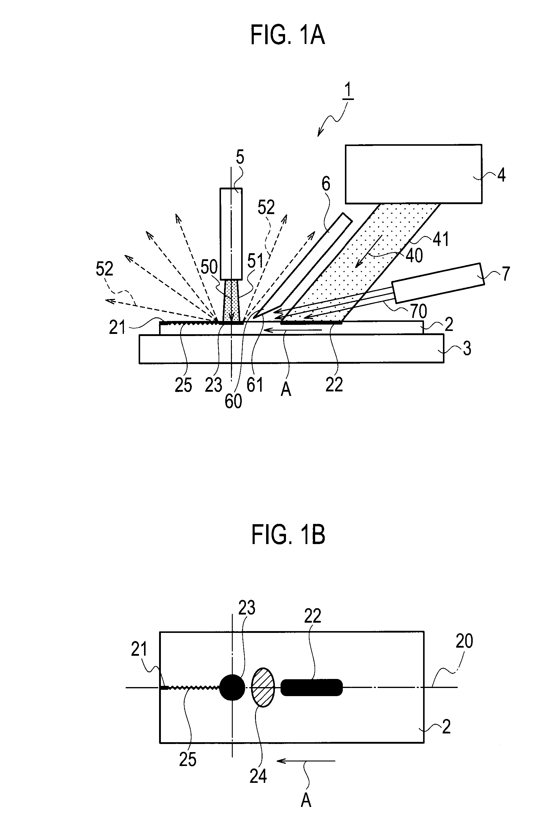
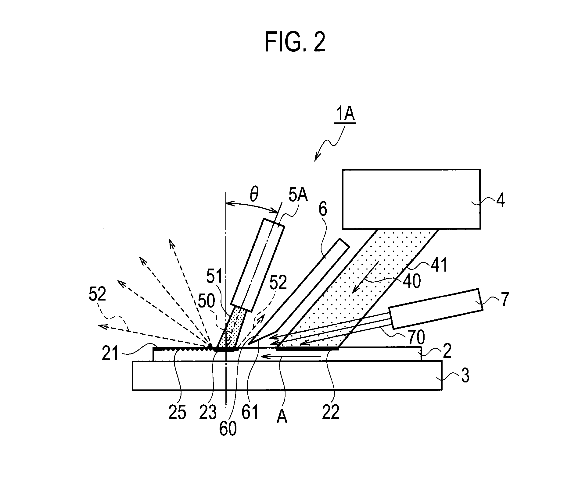
[0021]Referring to FIGS. 1A, 2, 3A and 4, any of devices 1,1A,1B,1C for cutting a glass plate 2 according to the present invention is comprised of a table 3 supporting the glass plate 2 thereon, a laser oscillator 4 for radiating a laser beam onto the glass plate 2, a cooling nozzle ...


PUM

PropertyMeasurementUnit
Angleaaaaaaaaaa
Angleaaaaaaaaaa
Brittlenessaaaaaaaaaa

Abstract

A device for cutting a brittle member such as a glass is comprised of a laser oscillator configured to radiate a laser beam through a first space onto a first region on the brittle member; a cooling nozzle configured to expel a cooling medium onto a second region distinct from the first region on the brittle member; a baffle so disposed as to leave a gap between the member and the baffle and to have the first region not enclosed by the baffle, and so directed as to deflect a flow of a splash and a mist originating in the second region away from the first region; and a gas nozzle configured to expel a gas toward the gap.

Description

CROSS-REFERENCE TO RELATED APPLICATIONS[0001]This application is a Continuation application of PCT International Application No. PCT / JP2012 / 066118 (filed Jun. 25, 2012), which is in turn based upon and claims the benefit of priority from Japanese Patent Application No. 2011-143035 (filed Jun. 28, 2011), the entire contents of which are incorporated herein by reference.BACKGROUND OF THE INVENTION[0002]1. Field of the Invention[0003]The present invention relates to a device and a method for cutting a brittle member and a cut-out brittle member.[0004]2. Description of the Related Art[0005]Brittle members such as glass plates could be cut not by a cutting tool but by applying thermal shock thereto. When a local heating means such as a laser beam for example is used to apply heat a glass plate and a cooling medium is then expelled onto regions where the local heating is given to create thermal shock therein, the regions given the thermal shock start to cleave. Thus, if a region that is i...

Claims


Application Information

Patent Timeline
IPC IPC(8): C03B33/09
CPCC03B33/091B23K26/127B23K26/147B23K26/1476B23K26/40B23K26/146B23K2103/50C03B33/03B23K26/14B23K26/38C03B33/033
Inventor YAMADA, JUNICHIKAWAGUCHI, NORIHITOWADA, YOSHIYUKIKUSUMI, TOMOOHASEGAWA, NORIAKINAKAYAMA, YUICHIROSAITOU, TOSHIAKI
Owner IHI CORP
Why Eureka
Try Eureka