Robot, robot control device, robot control method, and robot control program

Active Publication Date: 2014-04-24
PANASONIC INTELLECTUAL PROPERTY MANAGEMENT CO LTD
View PDF28 Cites 58 Cited by
  • Summary
  • Abstract
  • Description
  • Claims
  • Application Information

AI Technical Summary

Benefits of technology

[0009]One non-limiting and exemplary embodiment provides the above conventional problem and provide a gripped object-friendly, external environment-friendly, and safe robot, a robot control device, a robot control method, and a robot control program, each of which does not damage, drop nor tumble an object or a structure even when dynamics parameters (for example, a mass and an inertia moment of a gripped object) is switched at a time of gripping and releasing the object.

Problems solved by technology

This might damage a gripped object and might cause drop and tumbling of the gripped object or the like, thereby causing a problem from a viewpoint of the safety.

Method used


Image

  • Robot, robot control device, robot control method, and robot control program
  • Robot, robot control device, robot control method, and robot control program
  • Robot, robot control device, robot control method, and robot control program

Examples


first embodiment

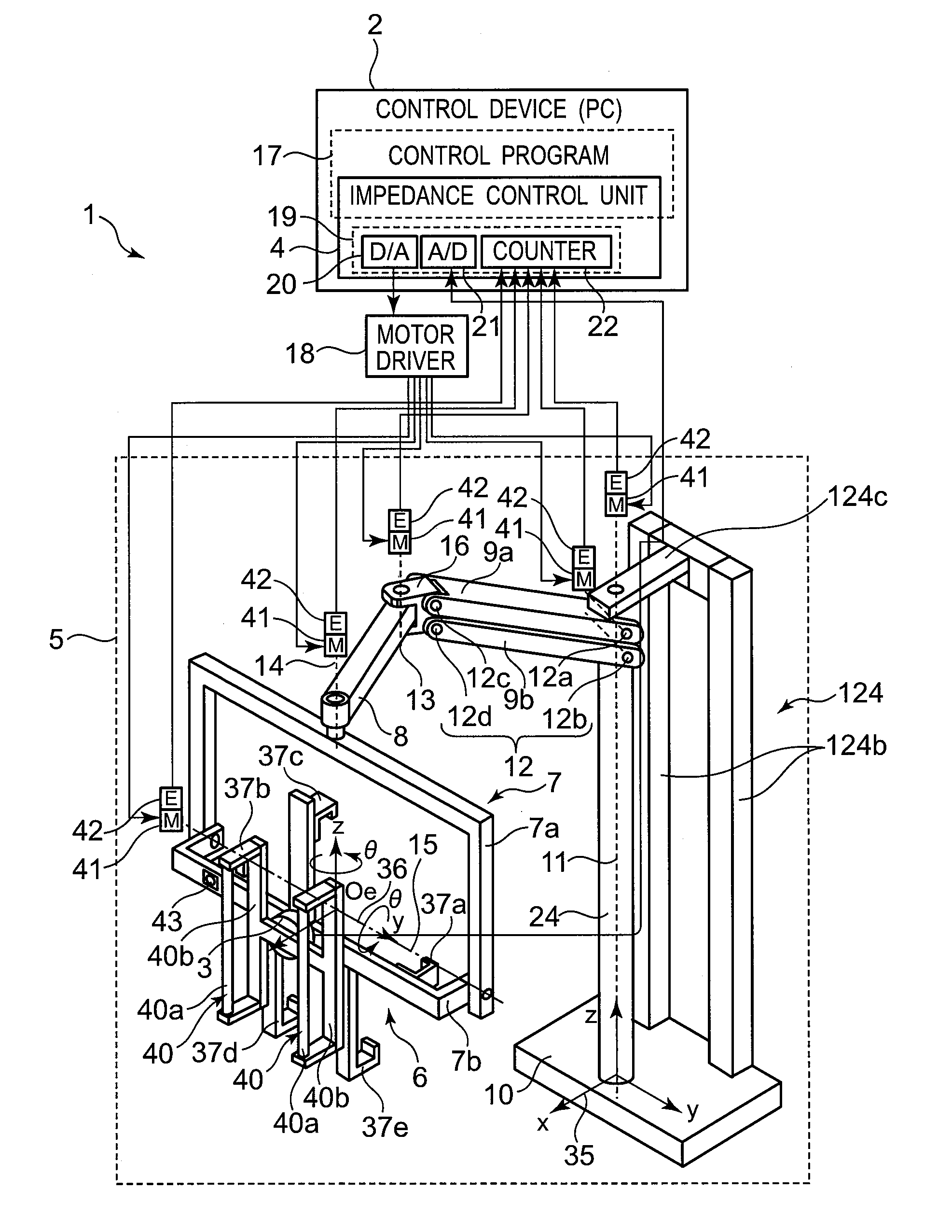
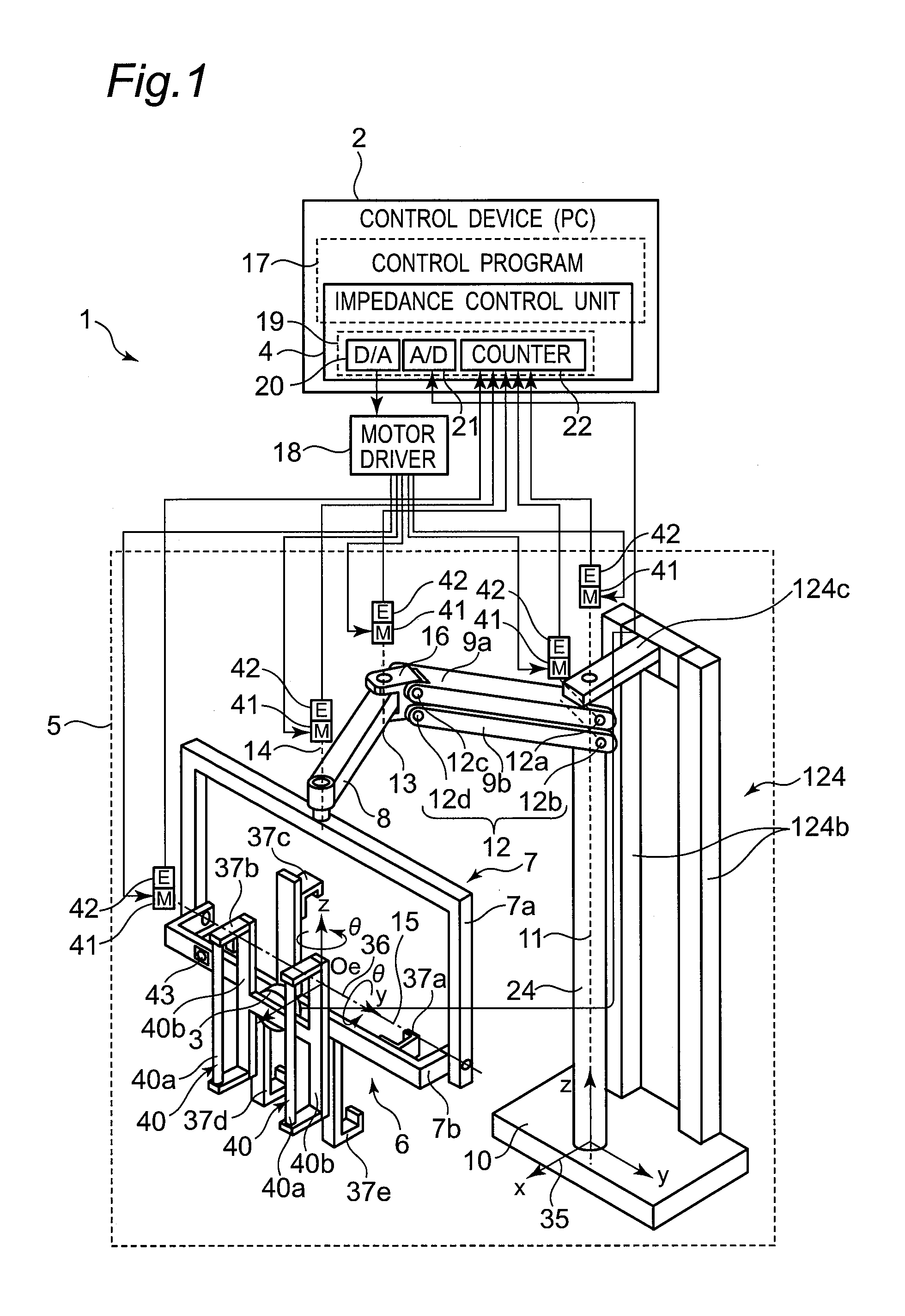
[0071]FIG. 1 illustrates the structure of a robot 1 according to a first embodiment of the present invention. The robot 1 includes a multi-joint robot arm 5, and a control device 2 that controls the operation of the multi-joint robot arm 5.

[0072]The control device 2 is structured by an ordinary personal computer in hardware. Further, parts of the control device 2 except for an input / output IF 19 of an impedance control unit (an impedance control section or a robot arm control section) 4 are realized in software as a control program 17 executed by the personal computer. Therefore, for example, a computer program having steps composing respective operations is stored readably in a recording medium such as a memory device (hard disc or the like), and the computer program is loaded into a temporary memory device (semiconductor memory or the like) of the computer so as to be run using a CPU and enable the respective steps to be executed.

[0073]The input / output IF 19 is structured by a D / A...

second embodiment

[0173]Since the basic constitution of the robot 1 according to a second embodiment of the present invention is similar to that in the first embodiment shown in FIGS. 1 and 2, the common portions are denoted by the same numbers as those in the first embodiment, and description thereof is omitted. Only different portions are described in detail below.

[0174]In the second embodiment, as shown in FIG. 10, the flow of the operational steps in the dynamics parameter switching unit 50 is different, and the dynamics parameters are switched separately at a plurality of stages.

[0175]After steps S70 and S71, at step S92, as the first stage of the switching, the dynamics parameter switching unit 50 switches the gravity term from gr(q) into grm (q) expressed by the following formula:

grm(q)=αgro(q)+(1−α)gr(q)  (9).

[0176]After step S73, at step S94, as the second stage of the switching, the dynamics parameter switching unit 50 switches the gravity term from grm(q) into gro(q).

[0177]Here, α denotes ...

third embodiment

[0180]Since the basic constitution of the robot 1 according to a third embodiment of the present invention is similar to that in the first embodiment shown in FIGS. 1 and 2, the common portions are denoted by the same numbers as those in the first embodiment, and description thereof is omitted. Only different portions are described in detail below.

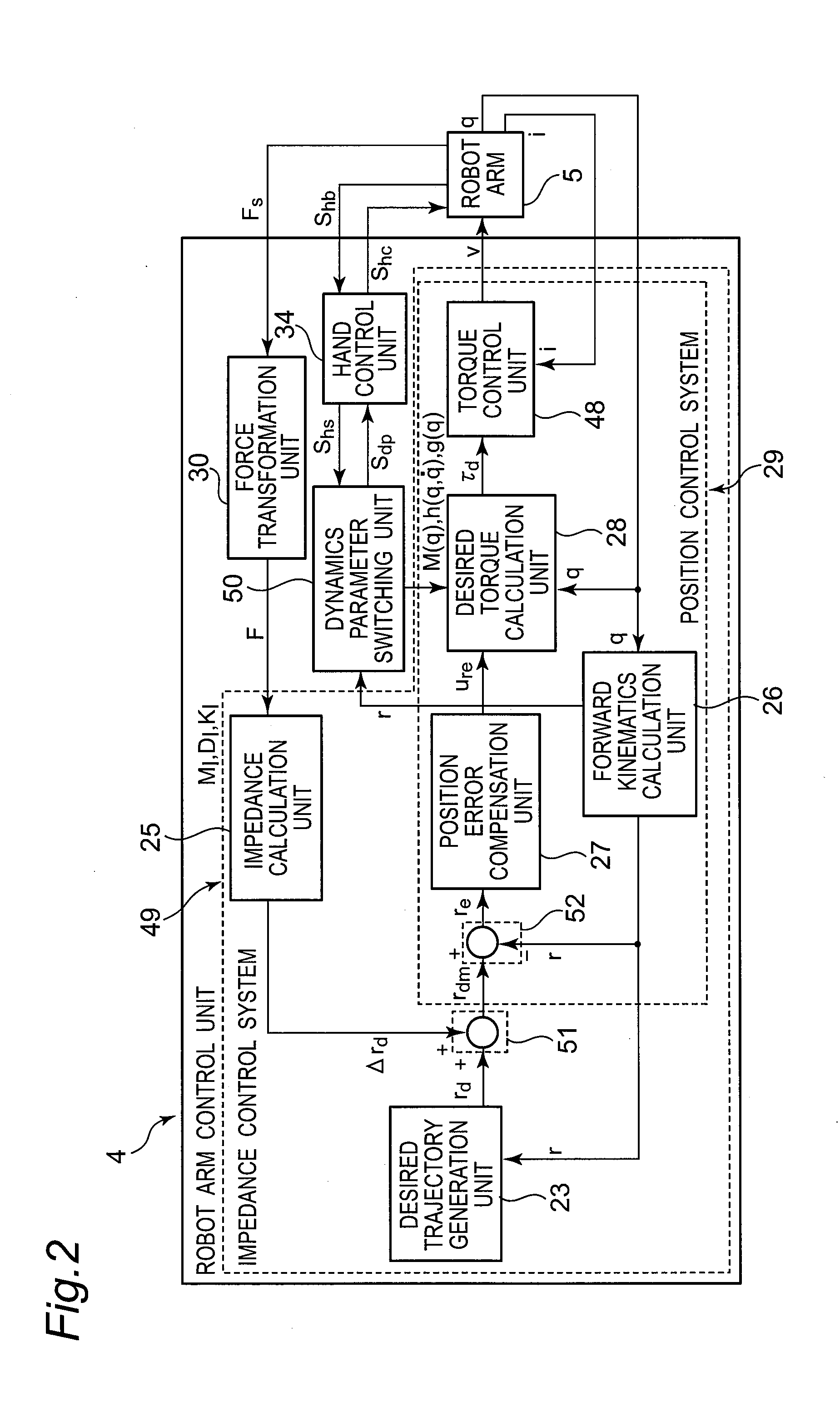
[0181]FIG. 11 is a block diagram illustrating a constitution of impedance control unit 4A of the robot according to the third embodiment of the present invention. The impedance control unit 4A according to the third embodiment is different from the impedance control unit 4 of the first embodiment in that an elastic force control unit (elastic force control section) 44 is newly added.

[0182]The elastic force control unit 44 receives the hand operation state signal Shs from the hand control unit 34, outputs the desired arm end point position and orientation correction output Δrdc to the second calculation section 52, and outputs a gain adjust...


PUM


Abstract

A robot having joints includes a position information acquiring section that acquires time series information about a robot position, speed information, or acceleration information, a dynamics parameter switching section that switches a gravity term component and an inertia force term component of a motion equation separately between dynamics parameters including dynamics parameter of the robot gripping no object and dynamics parameter including the object gripped by the robot which robot arm gripping the object, and a desired torque calculation section that outputs a desired robot joint torque value as a desired joint torque based on the motion equation after the dynamics parameter switching section switches the dynamics parameters and the time series information about the robot position, the speed information, or the acceleration information acquired by the position information acquiring section. The robot controls an operation of the robot based on an output from the desired torque calculation section.

Description

CROSS-REFERENCE TO RELATED APPLICATIONS[0001]This is a continuation application of International Application No. PCT / JP2012 / 007183, with an international filing date of Nov. 8, 2012, which claims priority of Japanese Patent Application No.: 2011-246217 filed on Nov. 10, 2011, the content of which is incorporated herein by reference.TECHNICAL FIELD[0002]The technical field relates to a robot for controlling an object conveyance operation, a robot control device, a robot control method, and a robot control program.BACKGROUND ART[0003]In recent years, domestic robots such as nursing-care robots or housework supporting robots are being actively developed. Further, as to industrial robots, robots that cooperate with persons are being actively developed due to spread of cell production plant or the like. Since such robots that cooperate with persons should live together with persons differently from conventional robots that operate in robot task areas separated from human areas, such robo...

Claims


Application Information

Patent Timeline
Patent Type & Authority Applications(United States)
IPC IPC(8): B25J9/16
CPCB25J9/1651B25J13/085G05B2219/37002G05B2219/40202G05B2219/41021
Inventor OKAZAKI, YASUNAO
Owner PANASONIC INTELLECTUAL PROPERTY MANAGEMENT CO LTD
Why Eureka
Try Eureka