
High-speed loading/unloading of objects

a high-speed, object technology, applied in the direction of measuring/indication equipment, structural/machine measurement, instruments, etc., can solve the problems of high maintenance costs, risk of damage to objects, and process still relatively slow

Active Publication Date: 2014-05-01
WILCO AG
View PDF1 Cites 6 Cited by
  • Summary
  • Abstract
  • Description
  • Claims
  • Application Information

AI Technical Summary

Benefits of technology

The patent describes an apparatus for loading and unloading objects, such as containers, using a rotary holder conveyor and a rotary transport arrangement. The apparatus allows for faster and smoother loading of multiple objects simultaneously, resulting in higher efficiency and productivity. The technical effects of this invention include faster and continuous loading, improved efficiency, and compact design.

Problems solved by technology

However these processes are still relatively slow, and depending on the geometry of the loading arrangement, are limited to loading and unloading about 60 objects per minute.
Furthermore, the movement of the robot is typically jerky, exhibiting high accelerations, which risks damaging the objects if they are fragile.
When utilising such a robot-based system, the only way to increase the throughput is, besides accelerating operation of the one robot, to use multiple robots, which is expensive and entails high maintenance costs and increased risk of parts breakage.

Method used


Image

  • High-speed loading/unloading of objects
  • High-speed loading/unloading of objects
  • High-speed loading/unloading of objects

Examples


Embodiment Construction

[0080]In the figures, like reference signs denote like parts.

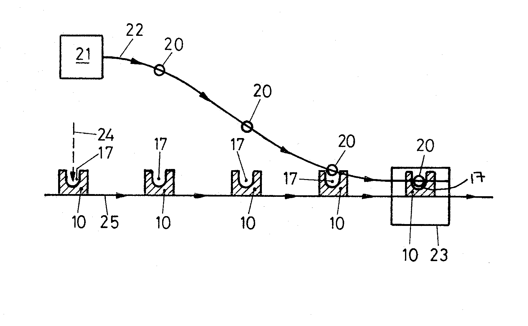
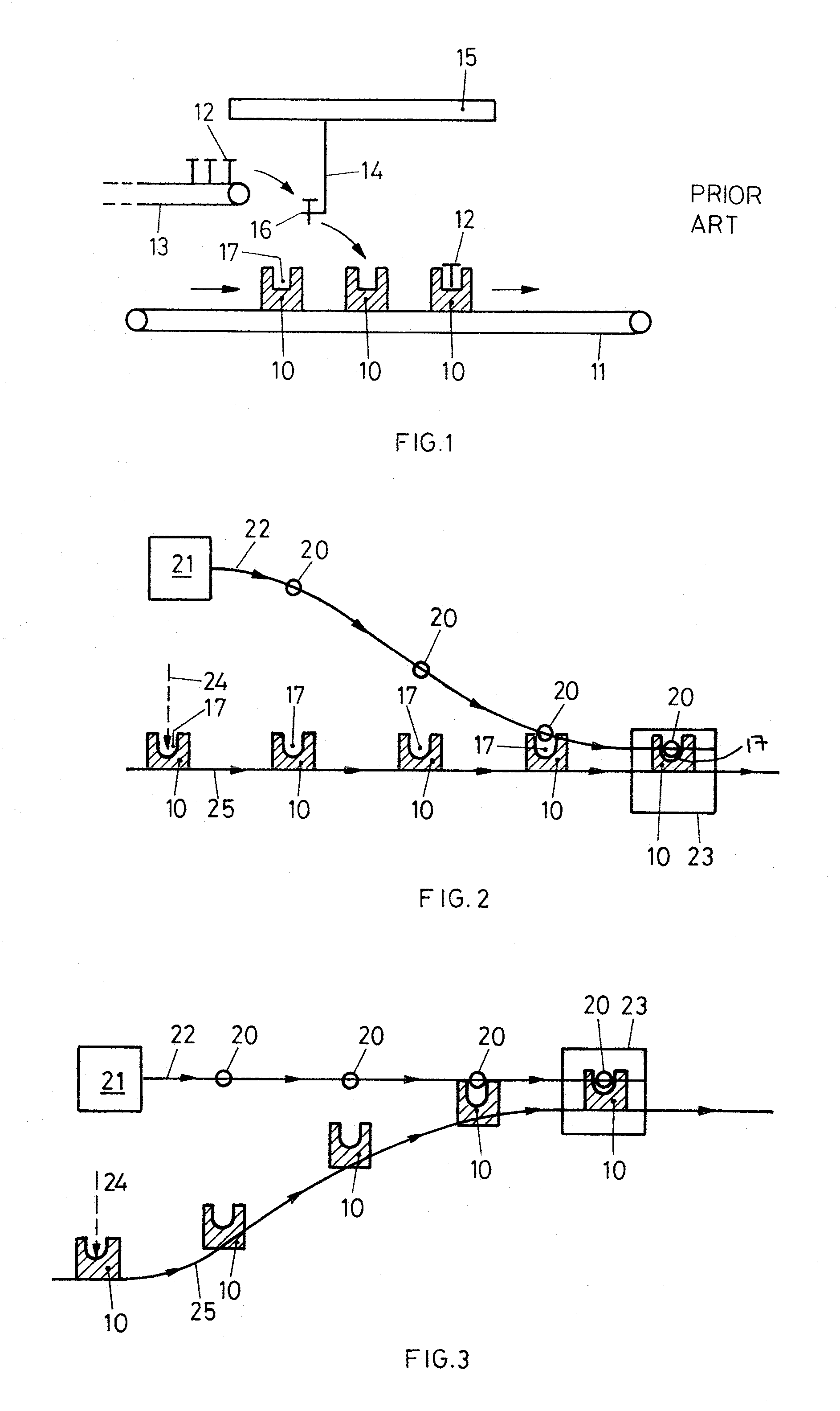
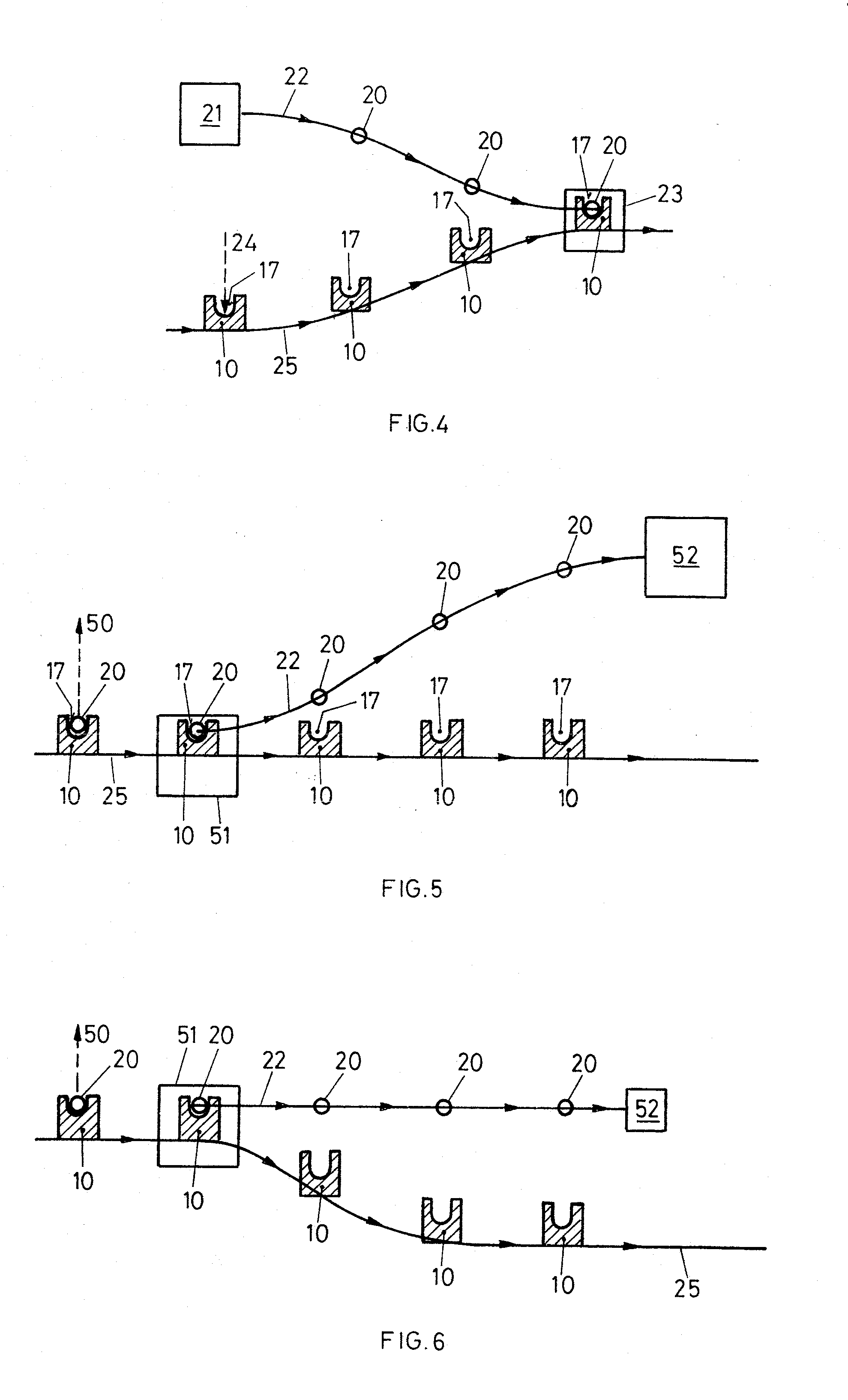
[0081]FIG. 2 illustrates schematically and most generically a first method for loading objects into holders according to the invention.

[0082]Objects 20, which may have been collected sequentially and continuously from a collecting area 21, are transported continuously along an object path 22 extending to loading area 23. Aside from when collecting the first or depositing the last object 20 in any given batch of operation, a plurality of objects 20 will be present on object path 22. Meanwhile, holders 10, each having at least one cavity 17, each cavity being configured to receive an object 20 and having a loading-direction 24, in which an object 20 is insertable into the cavity 17, are conveyed continuously along holder path 25 to, through, and from loading area 23.

[0083]Object path 22 approaches the conveyed holders 10, and also approaches holder path 25, as the holder path 25 and object path 22 approach the loading area 2...


PUM

PropertyMeasurementUnit
Shapeaaaaaaaaaa
Areaaaaaaaaaaa
Distanceaaaaaaaaaa

Abstract

The present invention relates to methods and an apparatuses for loading and unloading objects into / from corresponding cavities in holders at a high count rate. For loading, a plurality of objects are present on an object path which mutually converges with a holder path. For unloading, the object path mutually diverges from the holder path. Integration of this method and apparatus respectively into a method of manufacturing unleaky containers and a corresponding apparatus for leak testing containers is also proposed.

Description

BACKGROUND OF THE INVENTION[0001]In many production line situations, such as in manufacturing or testing situations, it is required to load objects such as containers into cavities in holders therefor, and subsequently to unload them from the holders. In comparison to merely transferring such objects from one conveyor to another, this loading in particular requires relatively precise positioning of the object such that it is deposited accurately into its cavity in its respective holder. This is all the more important when the object is fragile, such as e.g. in the case of glass syringes, since they must be handled and deposited gently to avoid breakage. Such holders are used as caddies to transport the objects through at least part of the manufacturing and / or testing system, and are commonly known in the field of leak testing as “pucks”. It should be noted that these holders thus do not form part of the consumer product being manufactured or tested, rather are used to assist in the ...

Claims


Application Information

Patent Timeline
IPC IPC(8): B65G17/12G01M3/00B65G17/30
CPCB65G17/30G01M3/329Y10T29/49764Y10T29/49829B65G17/12B65G17/20B65G37/00G01M3/00
Inventor LEHMANN, MARTIN
Owner WILCO AG
Learn More