Eureka AIR delivers breakthrough ideas for toughest innovation challenges, trusted by R&D personnel around the world.

Heat exchanger

a technology of heat exchanger and heat exchanger body, which is applied in the direction of indirect heat exchanger, stationary tubular conduit assembly, light and heating apparatus, etc., can solve the problems of reducing the pressure of the tank, and achieve the effect of reducing the running cost of the present invention, reducing the size of cooling facilities, and reducing the cost of facilities

Inactive Publication Date: 2014-05-01
NIPPON SANSO CORP
View PDF9 Cites 6 Cited by
  • Summary
  • Abstract
  • Description
  • Claims
  • Application Information

AI Technical Summary

Benefits of technology

The present invention allows for two types of heat exchange to take place in one container, eliminating the need for separate storage tanks and piping. This results in smaller and less expensive cooling facilities. The use of a low-temperature cooling medium for refrigerators reduces running costs compared to traditional liquefied gas cold sources.

Problems solved by technology

There arises such a problem that the temperature of a fuel tank exceeds the upper limit temperature thereof 85° C. when the temperature of hydrogen gas rises or a problem that the pressure of the tank decreases as the tank is cooled after being filled with hydrogen gas.

Method used


Image

  • Heat exchanger
  • Heat exchanger
  • Heat exchanger

Examples


Embodiment Construction

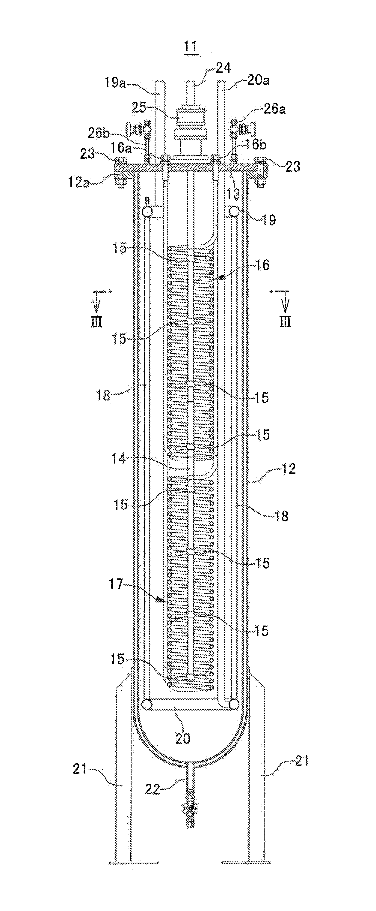
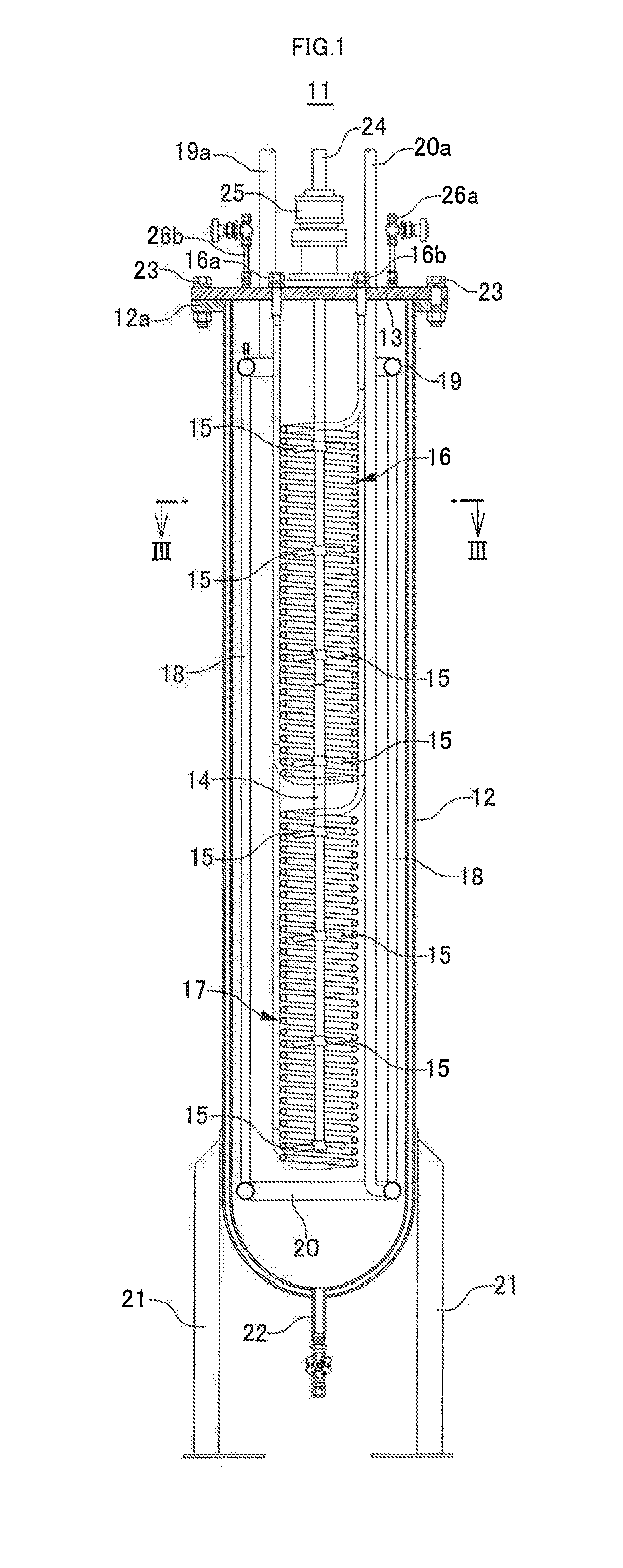
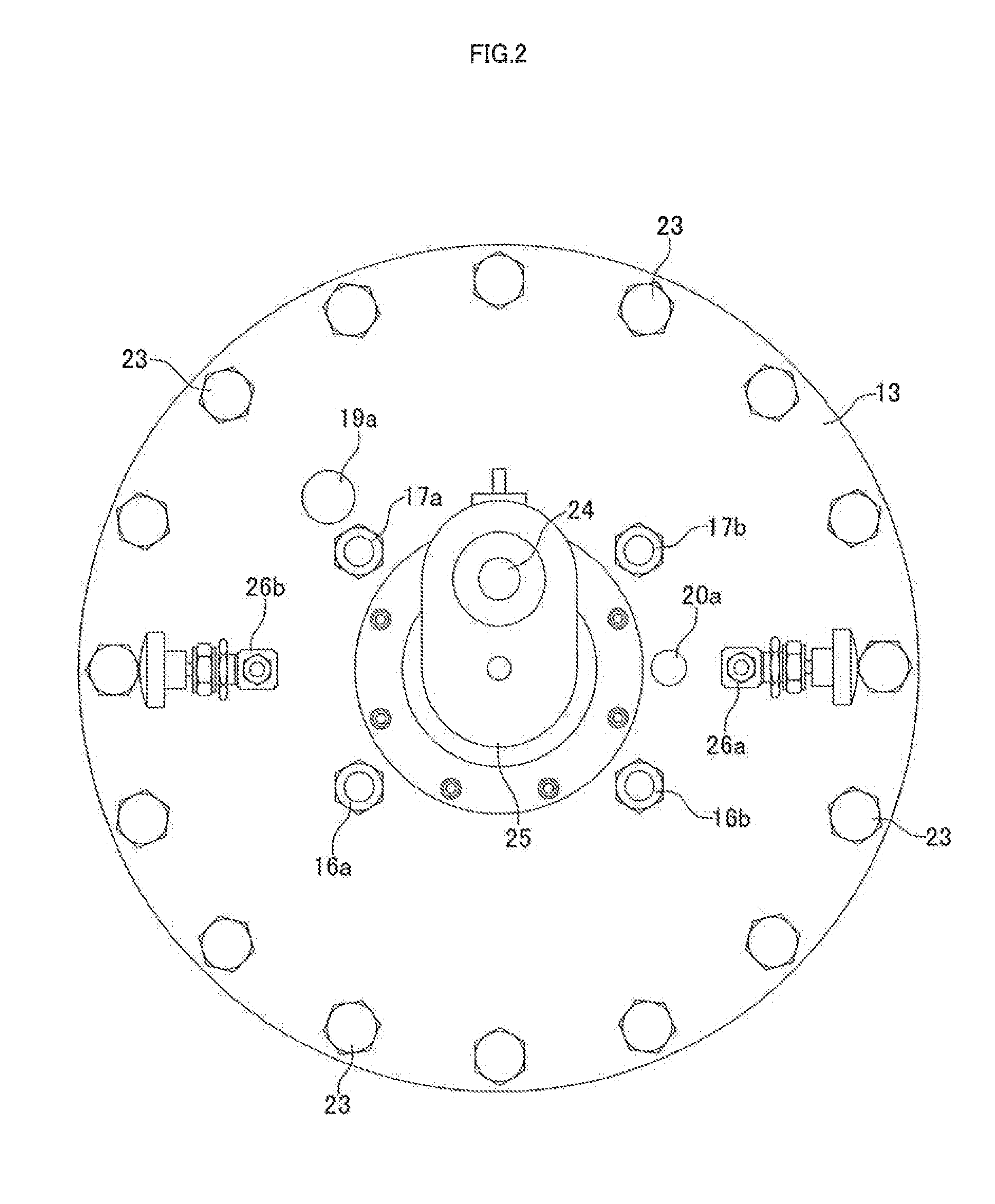
[0022]A heat exchanger 11 according to the embodiment comprises: a vacuum insulated double walled vertically long bottomed cylindrical container 12 which is filled with brine, a disk-shaped lid 13 closing an upper portion opening of the container 12, a rotation axis 14 which penetrates the center of the lid 13 to be arranged in the container 12 in the axis direction, a plurality of axial-flow propellers 15 provided on the rotation axis 14 in the vertical direction, a helical first hydrogen gas cooling tube 16 and a second hydrogen gas cooling tube 17 provided in a vertically two-stage structure around the rotation axis 14 and the propeller 15, and a plurality of cooling medium tubes 18 for cooling brine which are arranged around the first hydrogen gas cooling tube 16 and the second hydrogen gas cooling tube 17 in the axis direction.

[0023]The upper end and the lower end of each of the plurality of cooling medium tubes 18 for cooling brine are communicatively connected to an annular u...


PUM


Abstract

Provided is a heat exchanger in which heat exchange between a low-temperature cooling medium and brine and heat exchange between brine and hydrogen gas can be efficiently performed and downsizing of cooling facilities or reduction in facility cost can be attained. The heat exchanger comprises: a vacuum insulated container 12 which is filled with brine, a lid 13 closing an upper portion opening of the container, a rotation axis 14 arranged in the axis direction of the container, a propeller 15 provided on the rotation axis, a helical hydrogen gas cooling tube 16, 17 provided in a vertically two-stage structure around the rotation axis and the propeller, and a cooling medium tube 18 for cooling brine which is arranged around the hydrogen gas cooling tubes.

Description

TECHNICAL FIELD[0001]The present invention relates to a heat exchanger, and more particularly to a heat exchanger which is suitable for a heat exchanger for cooling hydrogen gas which is set up in a facility filling a fuel tank of a hydrogen automobile or the like with a hydrogen gas.BACKGROUND ART[0002]Hydrogen gas which is used as a fuel for a hydrogen automobile such as a fuel-cell automobile has the property that the temperature thereof rises due to the Joule-Thompson effect when it is adiabatically expanded at a portion such as a variety of valves or flowmeters provided along a pathway through which hydrogen gas flows. The temperature of hydrogen gas therefore rises due to the Joule-Thompson effect when hydrogen gas passes at a valve or the like provided along a pathway from a source of hydrogen gas supply through which a hydrogen automobile is filled with hydrogen gas. At the same time, the temperature of hydrogen gas rises also due to heat of compression when hydrogen gas is ...

Claims


Application Information

Patent Timeline
IPC IPC(8): F28D7/02F28D7/10
CPCF28F2250/08F28D2021/0047F28D7/103F28D7/024F28D7/10F28D7/16
Inventor KATAOKA, SHINJIWATANABE, NOBORU
Owner NIPPON SANSO CORP
Why Eureka
Eureka Blog
Learn More