Cogeneration system

a cogeneration system and cogeneration technology, applied in combustion-air/fuel-air treatment, sustainable manufacturing/processing, lighting and heating apparatus, etc., can solve the problems of engine stoppage risk, the inability to start the cooling water pump immediately after the engine is started, etc., to avoid the engine being stopped, energy supply from the battery will not be excessively consumed, and energy can be saved.

Inactive Publication Date: 2009-04-30
HONDA MOTOR CO LTD
View PDF13 Cites 13 Cited by
  • Summary
  • Abstract
  • Description
  • Claims
  • Application Information

AI Technical Summary

Benefits of technology

[0008]Thus, after a power outage, the engine can be cooled at the same time the engine is started. A cooling water malfunction, in which the engine reaches a state of high load immediately after starting, and the temperature of the cooling water reaches or exceeds a predetermined value, is accordingly less likely to occur. Therefore, it is possible to avoid the engine being stopped as a result of a cooling water malfunction.
[0009]Preferably, an inverter unit for changing a rate at which the motor rotates is disposed in a system for supplying electricity from the electricity supplying means to the motor. As long as the rate at which the cooling water pump rotates can be changed, it is thus possible to set a flow of cooling water that is ideal for the temperature of the engine. Accordingly, the energy supplied by the battery will not be excessively consumed, and energy can be conserved.
[0010]Desirably, the inverter unit is provided with a first input terminal for inputting power from the electricity supplying means, a first output terminal for outputting power to the motor, a second input terminal for inputting power from the generator, and a second output terminal for outputting power to the exterior. When the inverter unit is provided for changing the voltage and frequency of the electrical energy generated by the generator and outputting the energy to the exterior, it is not necessary to provide a separate inverter unit for changing the rate at which the cooling water circulation pump rotates. Therefore, the facility cost can be decreased. Additionally, the number of components can be reduced.
[0011]In a preferred form, the electricity supplying means is preferably a battery provided for starting the engine, or a battery provided solely for starting the cooling water pump. As a result, the engine can be restarted using simple and inexpensive means.
[0012]The battery is preferably disposed in an engine accommodation part, in which the engine is stored, or a unit accommodation part that has the exhaust heat exchanger. Therefore, an existing battery can be used effectively.

Problems solved by technology

In a case where the electrical energy generated by the generator is to be used, the electrical energy will be supplied after the warm-up operation of the engine has concluded; therefore, the cooling water pump cannot be started immediately after the engine has been started.
For this reason, when the engine is operated in a power outage and the engine load increases immediately after the engine has started, a cooling water malfunction will occur from the temperature of the cooling water reaching or exceeding a predetermined value, and a risk of engine stoppage will be presented.

Method used


Image

  • Cogeneration system
  • Cogeneration system
  • Cogeneration system

Examples


Embodiment Construction

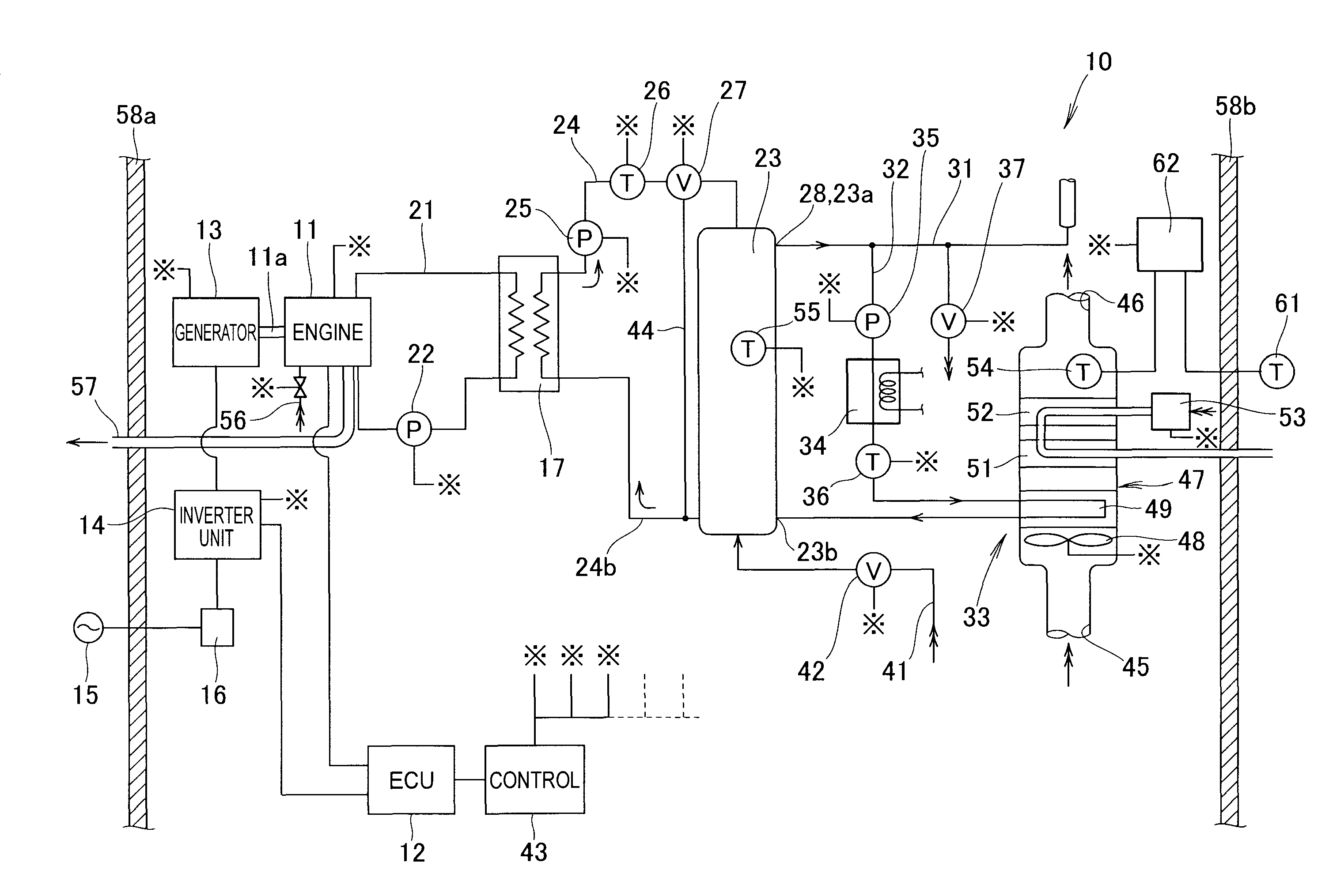
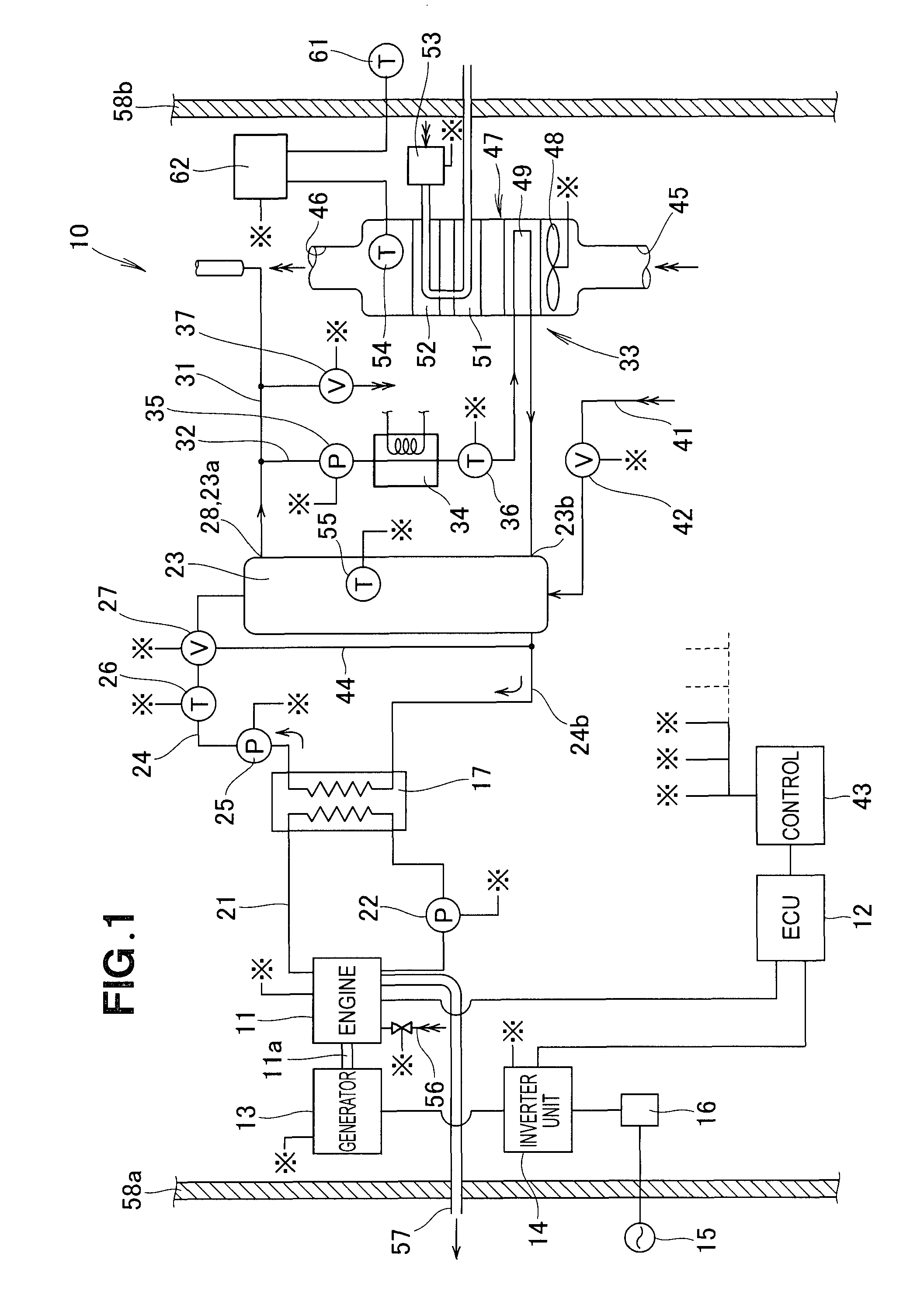
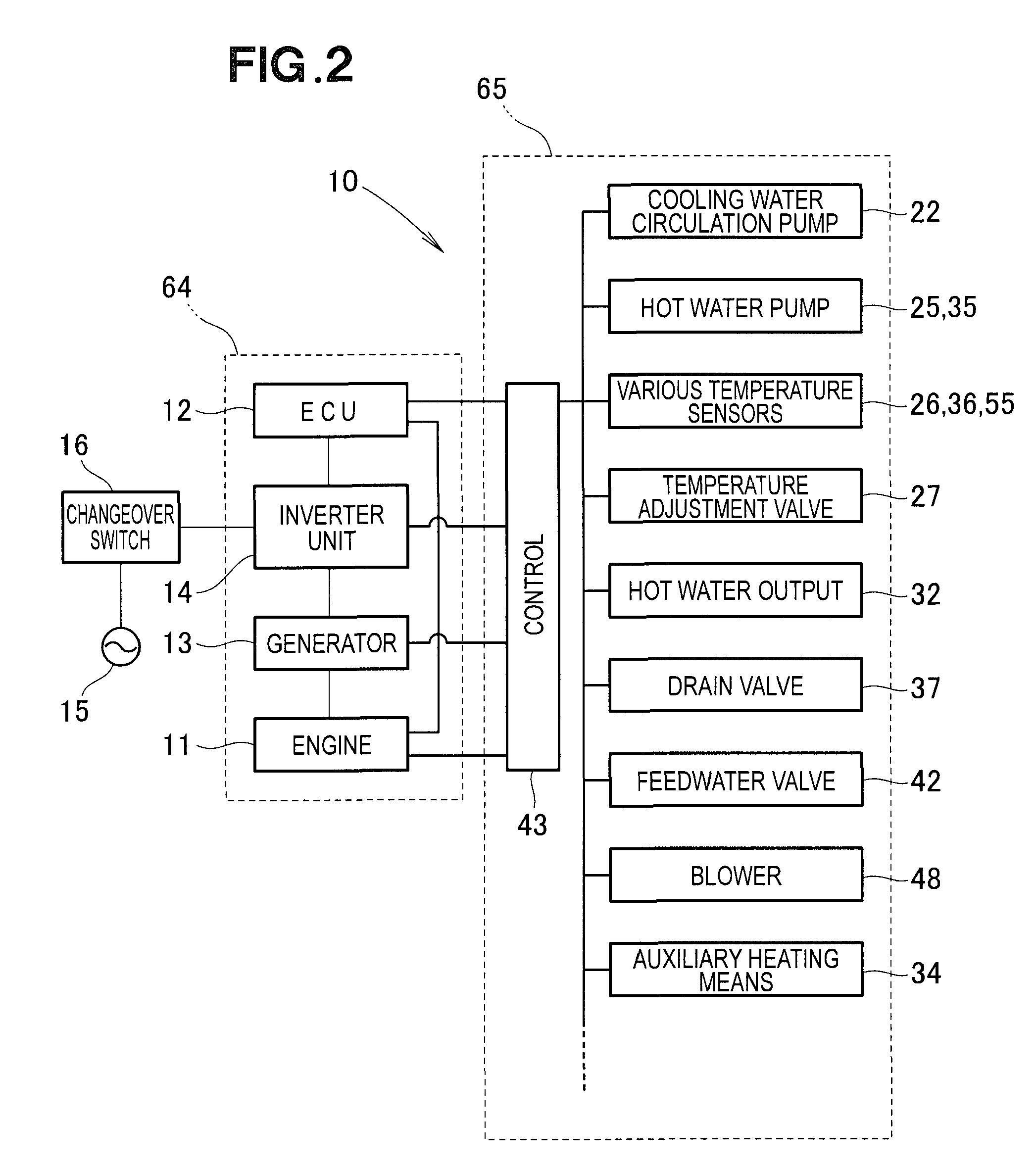
[0021]As shown in FIG. 1, a cogeneration system 10 has an engine 11 used as a prime mover, an ECU 12 for controlling the engine 11, and a generator 13. The generator 13 is linked on an output shaft 11a of the engine 11, and electrical energy is generated by the drive of the engine 11.

[0022]An inverter unit 14 is connected to an output terminal of the generator 13. A changeover switch 16 is provided between the inverter unit 14 and an external commercial power supply 15, and stops the generated electrical energy from being supplied to the external commercial power supply 15 outside of predetermined periods.

[0023]An exhaust heat exchanger 17 increases the temperature of cooling water using exhaust gas released by the engine 11 as a heat source. A cooling water circulation channel 21 links the engine 11 and the exhaust heat exchanger 17, and cooling water for cooling the engine 11 is circulated therethrough. A cooling water circulation pump 22 is disposed along the cooling water circul...


PUM


Abstract

A cogeneration system is disclosed. The system has a cooling water circulation channel for returning cooling water of the engine to the engine after some of the cooling water has been removed. The cooling water circulation channel is provided with a cooling water pump for pressure-feeding the cooling water; electricity supplying means; and a control part for performing a control so that electrical energy is supplied from the electricity supplying means to a motor for driving the cooling water pump when a power outage signal is received.

Description

FIELD OF THE INVENTION[0001]The present invention relates to an improvement to a cogeneration system in which a generator driven by the operation of an engine is used to produce electrical energy, and cold water is turned into hot water using heat released by the engine.BACKGROUND OF THE INVENTION[0002]There are known cogeneration systems in which a generator driven by the operation of an engine is used to produce electrical energy, and an exhaust heat exchanger is used to turn cold water into hot water, as disclosed in Japanese Patent Application Laid-Open Publication No. 2006-348948 (JP 2006-348948 A).[0003]A cogeneration system disclosed in JP 2006-348948 A is provided with an engine; a generator that generates electricity, the generator being driven by the operation of the engine; an exhaust heat exchanger for using exhaust heat released from the engine to heat cold water into hot water; a cooling water circulation channel, through which cooling water circulates, and which is di...

Claims


Application Information

Patent Timeline
Patent Type & Authority Applications(United States)
IPC IPC(8): H02K7/18F02M31/08F28D15/00
CPCF01P2031/30F02B63/04Y02T10/166F02G2260/00Y02E20/14F02G5/04Y02P80/15Y02T10/12
Inventor YURI, NOBUYUKIWAKITANI, TSUTOMU
Owner HONDA MOTOR CO LTD
Why Eureka
Try Eureka