Tubular Member Coupling and Lining Systems and Methods

a technology of tubular member and coupling system, which is applied in the direction of wellbore/well accessories, drilling accessories, fluid removal, etc., can solve the problems of significant wear of production tubing, more difficult and costly replacement than a coupler, and the coating may quickly wear away

Inactive Publication Date: 2014-05-01
INNOVATIVE TOOL TECH
View PDF10 Cites 8 Cited by
  • Summary
  • Abstract
  • Description
  • Claims
  • Application Information

AI Technical Summary

Benefits of technology

[0031]whereby the rigid liner fluidly communicates the first and second tubular members via an internal passage extending through the rigid liner, and accommodates passage of a sucker rod string through the internal passage of the rigid liner to protect an inner surface of the first tubular member from contact with the sucker rod string.

Problems solved by technology

A common problem in such installations is that the sucker rod string does not extend entirely linearly in the wellbore, and accordingly box couplings between the rods, which are of larger outer diameter than the rods themselves and thus form the radially outermost extents of the string, will tend to bump or rub against the production tubing wall during the driven rotation of the rod string and thus cause significant wear to the production tubing.
One prior art solution has been to bond elastomeric materials to the hard outer surfaces of sucker rod couplers to reduce wear to the tubing, which is more difficult and costly to replace than a coupler.
However, the coating may quickly wear away, requiring frequent replacement or recoating of sucker rod couplers.
Installation of the prior art wear-prevention solutions can be time intensive, and thus inefficient.

Method used


Image

  • Tubular Member Coupling and Lining Systems and Methods
  • Tubular Member Coupling and Lining Systems and Methods
  • Tubular Member Coupling and Lining Systems and Methods

Examples


Embodiment Construction

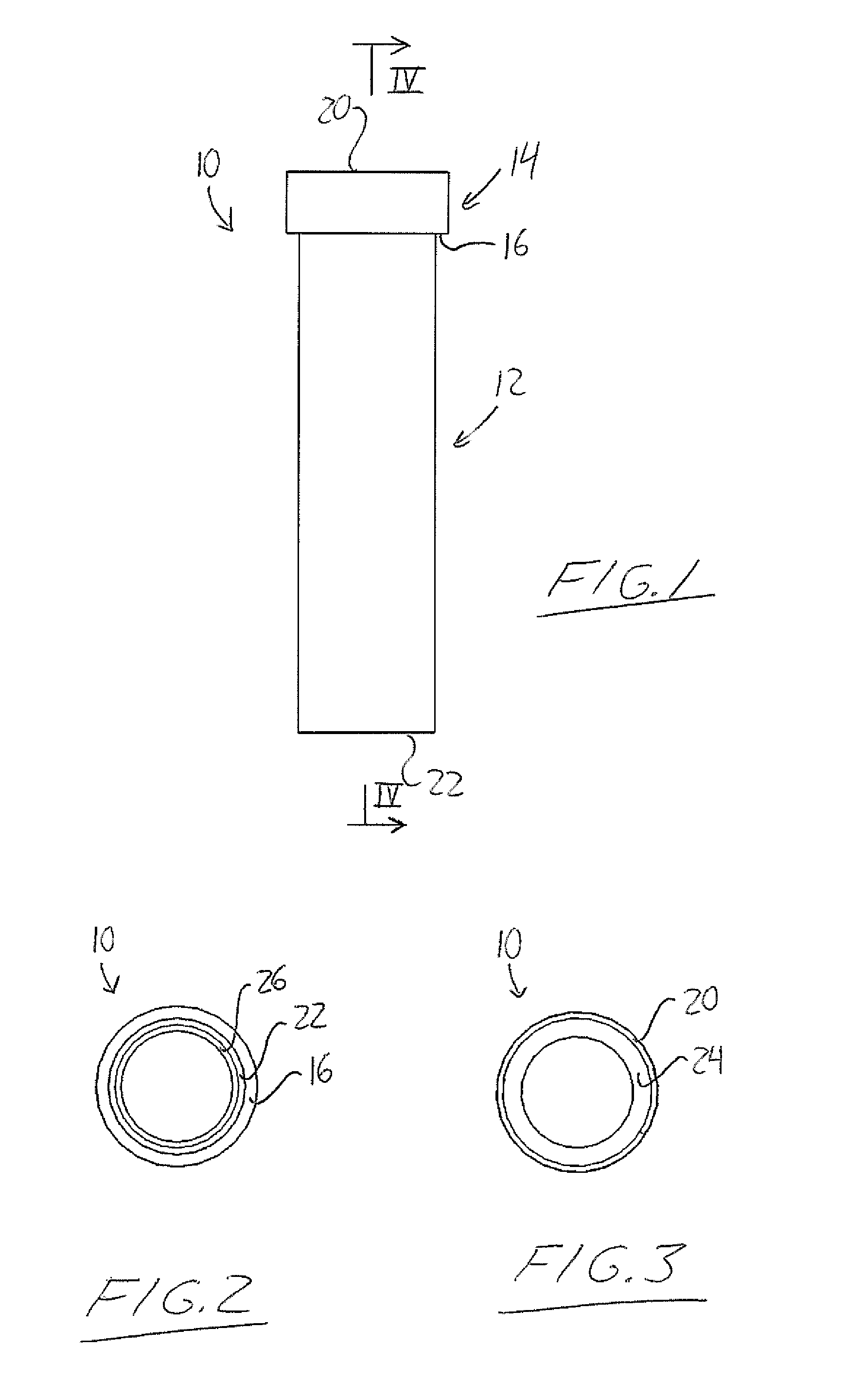
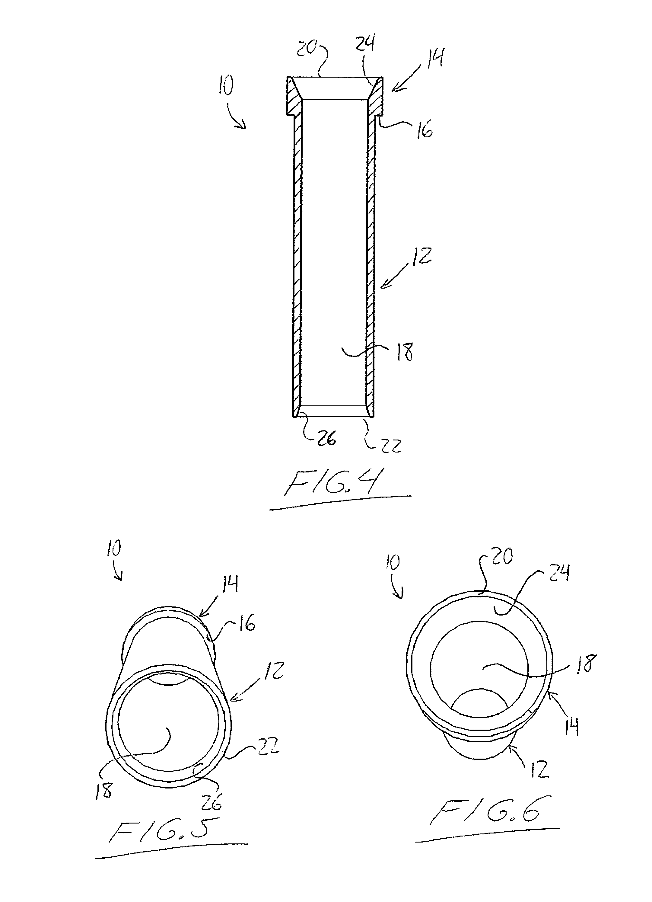
[0046]With reference to FIG. 7, the drawings show an embodiment of a liner insert 10 arranged to be placed within a section of a production tubing string 100 for a well so that a sucker rod string 102 to be extended downward through the tubing 100 for operation of a downhole pump in the wellbore is prevented from contacting the internal surface of the tubing string 100 at the location of the insert 10. The assembled conventional tubing string 100 features adjacent tube joints or sections 104, 106 situated one over the other in axial alignment and coupled together by means of an internally threaded collar or box coupler 108 that engages an externally threaded lower upset portion 110 of the upper tubing section 104 and an externally threaded upper upset end portion 112 of the lower tubing section 106. These conventional EUE (externally upset end) tubing sections are each of uniform inner diameter from end to end, and of uniform outer diameter between the opposite externally threaded u...


PUM


Abstract

For use in assembling a tubing string for a production well, a rigid pre-formed liner is configured for simple drop-in place installation at each tubing joint during assembly of the tubing string in to protect the inside of the tubing string from wear caused by operation of a sucker rod inside the same. At a threaded connection in the finished tubing string, where an externally threaded top end of a section of production tubing is engaged with an internally threaded bottom end of a box coupler or collar, the tubular portion of a respective liner hangs downward from a larger-diameter collar portion of the liner that sits atop the annular top end of the section of production tubing. The liner is installed by simply dropping its tubular portion into the section of tubing and then threading the box coupler onto the section tubing around the upper end of the liner.

Description

CROSS REFERENCE TO RELATED APPLICATIONS[0001]This application claims benefit under 35 U.S.C. 119(e) of Provisional Application Ser. No. 61 / 721,248, filed Nov. 1, 2012.FIELD OF THE INVENTION[0002]The present invention relates generally to well tube liners for use in well production, and more particularly to well tube liner inserts configured for easy drop-in installation during joining of tubing sections or joints for the purpose of providing a buffer between the tubing and a sucker rod deployed therein to operate downhole equipment.BACKGROUND OF THE INVENTION[0003]In pumping of fluids from a wellbore for production to the surface, a string of sucker rods connected end to end is used as a mechanical link between drive equipment at the surface and a downhole pump in the wellbore for driven operation thereof. Conventionally, sucker rods are typically each externally threaded at pin ends of the rod and are interconnected by internally threaded box couplings each threadingly receiving en...

Claims


Application Information

Patent Timeline
Patent Type & Authority Applications(United States)
IPC IPC(8): E21B17/042E21B17/10
CPCE21B17/1007E21B17/042
Inventor WOLLMANN, ARNOLD
Owner INNOVATIVE TOOL TECH
Why Eureka
Try Eureka