
Image output system, image signal generation apparatus and recording medium

Inactive Publication Date: 2014-05-01
RICOH KK
View PDF5 Cites 4 Cited by
  • Summary
  • Abstract
  • Description
  • Claims
  • Application Information

AI Technical Summary

Benefits of technology

The present invention provides an image output system, an image signal generation apparatus and a recording medium that stores a program that substantially overcome the limitations and disadvantages of the related art. The technical effect of the invention is to switch the channel that outputs the image signal to an image output unit based on the states of multiple channels, rather than randomly switching channels. This results in more efficient use of resources and improved user experience. Additionally, the system includes an information display screen related to the currently outputting channel and a display state retaining unit configured to retain a state related to the information display screen. The channel is switched only after waiting for a predefined change of the state related to the information display screen, which ensures that the information displayed on the screen is retained and utilized appropriately.

Problems solved by technology

As the above progress is made in terms of the variety of available input sources, it has become difficult for a user to keep track of which input source is currently being used, and it has become cumbersome for a user to change channels.
At this time, if an auto-detection function such as the auto-search of Patent Document 1 is activated, then there is a possibility of a problem in which the above alarm display screen cannot be displayed appropriately.
For example, if an error occurs in the USB storage or the USB storage is removed, then as a response, the USB storage is un-mounted.
As a result, the alarm display screen related to an error in the USB storage or to the removing of the USB storage is not reported to the user, and there is a possibility that the error is not noticed by the user and left unresolved.[Patent Document 1] Japanese Patent Application Publication No. 2007-327987

Method used


Image

  • Image output system, image signal generation apparatus and recording medium
  • Image output system, image signal generation apparatus and recording medium
  • Image output system, image signal generation apparatus and recording medium

Examples


Embodiment Construction

[0023]In the following, embodiments of the present invention will be described with reference to the accompanying drawings.

[0024]The present invention is not limited to the following embodiments. Note that in the following embodiments, as an example of an image output system, a projector 110 is used in the description.

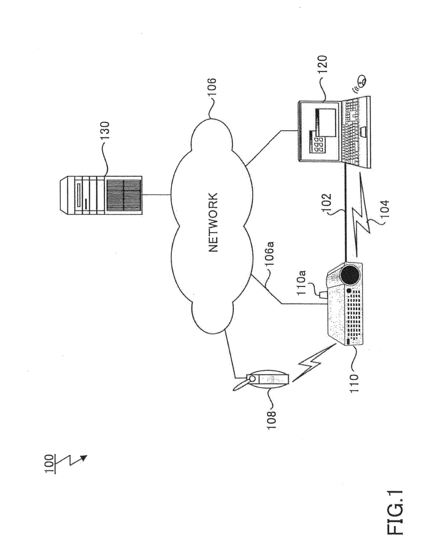
[0025]FIG. 1 is a drawing illustrating a connection configuration 100 of the projector 110 of the present embodiment. The projector 110 shown in FIG. 1 is an image output apparatus which projects an inputted image or an image generated from an obtained file onto a screen, etc. Regarding an image projection method, it is not limited to a specific method, and various appropriate methods can be used such as a liquid crystal method, a CRT (Cathode Ray Tube) method, a DLP (Digital Light Processing) method, an LCOS (Liquid Crystal On Silicon) method, etc. The projector 110 also includes a network interface such as a NIC (Network Interface Card), a wireless LAN (Local Area Ne...


PUM


Abstract

An image output system includes plural channels from each of which an image signal is output, a switching unit for switching the channel that outputs the image signal to an image output unit based on connection states of the plural channels, an information display generation unit for generating the image signal of an information display screen related to the currently outputting channel, and a display state storing unit for storing a display state related to the information display screen, the display state including a “display-ON” state and a “display-OFF” state. In a case where there is a change in the connection state of the currently outputting channel, when there is the information display screen whose display state is the “display-ON” state, the switching unit switches the channel after waiting for a predefined change in the display state related to the information display screen.

Description

BACKGROUND OF THE INVENTION[0001]1. Field of the Invention[0002]The disclosures herein generally relate to an image output system, an image signal generation apparatus and a recording medium. To be more in detail, the disclosures herein relate to an image output system, an image signal generation apparatus and a recording medium that stores a program, for outputting images by switching inputs of multiple channels.[0003]2. Description of the Related Art[0004]In recent years, projectors have made progress in terms of variety of available input sources. For example, some projectors are compatible with various video interfaces such as VGA (Video Graphics Array), HDMI (High-Definition Multimedia Interface), DVI (Digital Visual Interface), and DisplayPort (registered trademark). Also, some projectors are capable of projecting an image via a network using a network connection by a wired line or a wireless LAN, or are capable of projecting an image from a file stored in a USB (Universal Ser...

Claims


Application Information

Patent Timeline
IPC IPC(8): H04N5/44
CPCH04N5/44591H04N21/44227H04N21/436H04N21/482H04N21/47217H04N21/4882H04N5/44H04N21/4316H04N21/47
Inventor HAGIWARA, ARITAKAYUKUMOTO, REIJIANNAKA, HIDEKUNISUGIURA, YOKO
Owner RICOH KK
Features
  • Generate Ideas
  • Intellectual Property
  • Life Sciences
  • Materials
  • Tech Scout
  • Unparalleled Data Quality
  • Higher Quality Content
  • 60% Fewer Hallucinations
Learn More