Lens holder driving device capable of ensuring linearity of wide range in driving response

Active Publication Date: 2014-05-01
MITSUMI ELECTRIC CO LTD
View PDF4 Cites 12 Cited by
  • Summary
  • Abstract
  • Description
  • Claims
  • Application Information

AI Technical Summary

Benefits of technology

[0012]It is therefore an exemplary object of the present invention to provide a lens holder d

Problems solved by technology

This is because the lens holder 14 easily becomes brittle if a compounding

Method used


Image

  • Lens holder driving device capable of ensuring linearity of wide range in driving response
  • Lens holder driving device capable of ensuring linearity of wide range in driving response
  • Lens holder driving device capable of ensuring linearity of wide range in driving response

Examples


Example

First Exemplary Embodiment

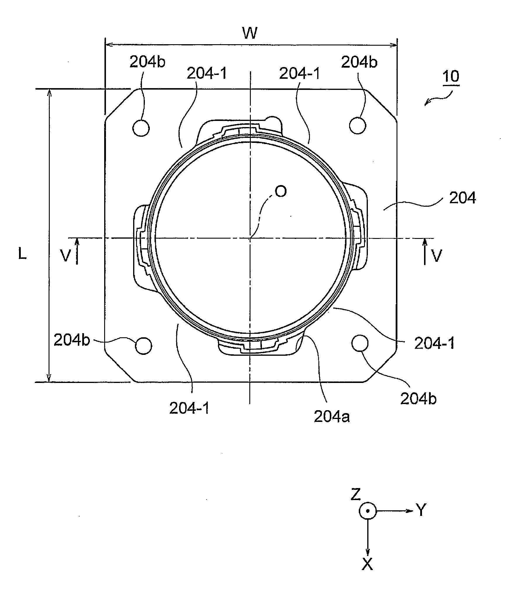
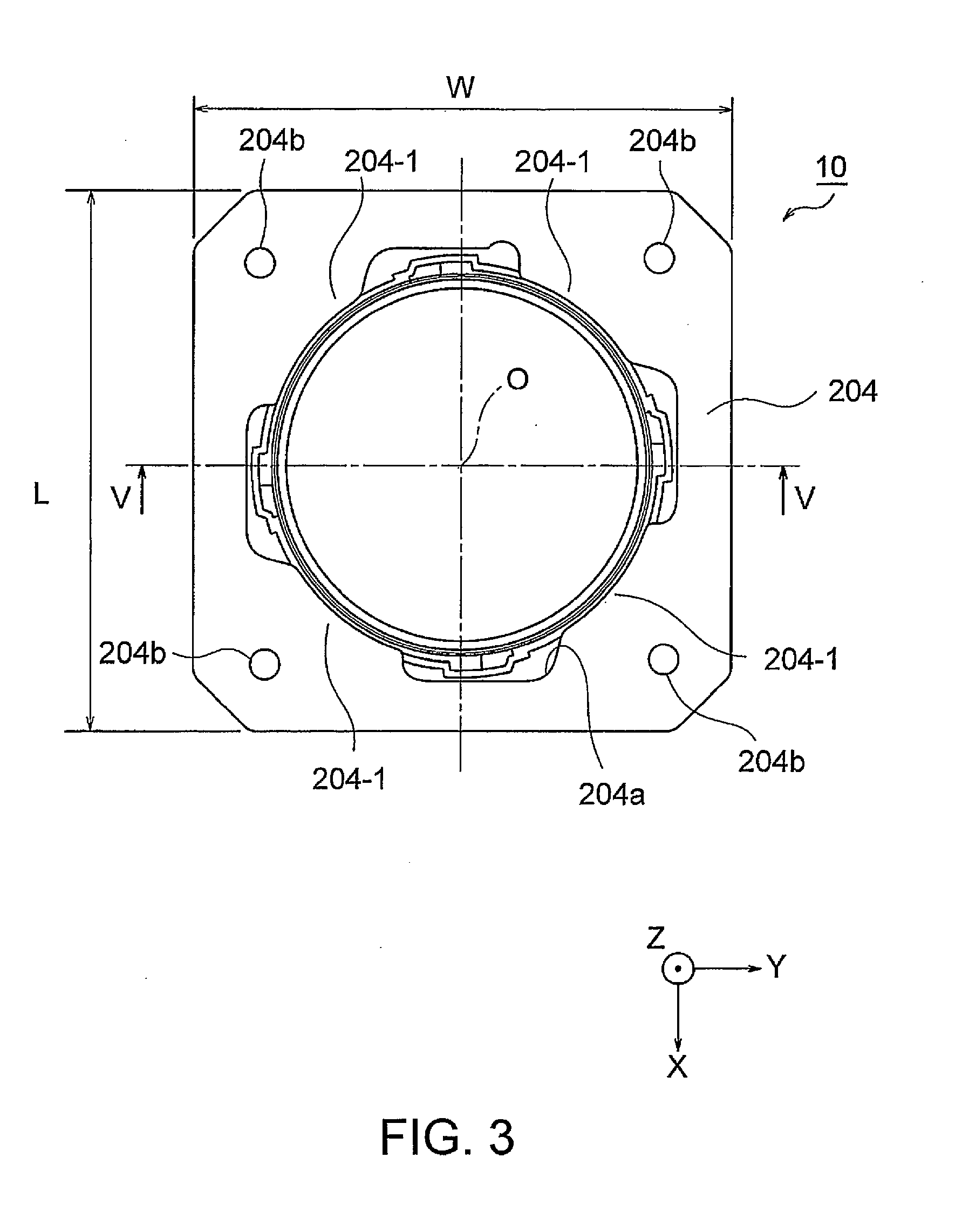
[0046]Referring to FIGS. 3 through 6, the description will proceed to a lens holder driving device 10 according to an exemplary embodiment of this invention. FIG. 3 is a plan view showing the lens holder driving device 10 and FIG. 4 is a left side view of the lens holder driving device 10. FIG. 5 is a cross-sectional view taken on line V-V of FIG. 3. FIG. 6 is an exploded perspective view of the lens holder driving device 10.

[0047]Herein, in the manner shown in FIGS. 3 through 6, an orthogonal coordinate system (X, Y, Z) is used. In a state illustrated in FIGS. 3 through 6, in the orthogonal coordinate system (X, Y, X), an X-axis direction is a fore-and-aft direction (a depth direction), a Y-axis direction is a left-and-right direction (a width direction), and a Z-axis direction is an up-and-down direction (a height direction). In addition, in the example being illustrated in FIGS. 3 through 6, the up-and-down direction Z is a direction of an optical axis O...

Example

Second Exemplary Embodiment

[0089]The above-mentioned lens holder driving device 10 according to the first exemplary embodiment reduces the contact area by forming the wrinkles 146a on the upper surfaces of the holder upper protrusion portions 146 without making a change to the material of the lens holder 14.

[0090]In comparison with this, a lens holder driving device according to a second exemplary embodiment of this invention further makes a change to the material of the lens holder 14. That is, a molded material in which a conductive material is mixed is used as the molded material of the lens holder 14. With this structure, a volume resistivity of the lens holder 14 was equal to 1×10¹¹ [Ω·cm].

[0091]FIG. 14 is a view showing effect of improvement in an upper hysteresis amount (μm) in the vicinity of the maximum stroke. In FIG. 14, a left side shows an upper hysteresis amount (μm) in the related art (NORMAL), a central portion shows an upper hysteresis amount (μm) in the above-menti...


PUM


Abstract

A lens holder driving device includes a lens holder in which a lens assembly is mounted, a driving coil fixed to the lens holder at outside circumference thereof, an outer yoke including an outer hollow cylindrical portion and an ring-shaped end portion disposed an upper end of the outer hollow cylindrical portion, a magnet disposed to an inner wall surface of the outer hollow cylindrical portion so as to be opposite to the driving coil, an elastic member supporting the lens holder in a direction of an optical axis shiftably, and a base disposed at a lower side of the lens holder. The lens holder driving device includes a contact area reduction arrangement reducing a contact area between the ring-shaped end portion of the outer yoke and an upper end portion of the lens holder.

Description

[0001]This application is based upon and claims the benefit of priority from Japanese Patent Application No. JP 2012-241069, filed on Oct. 31, 2012, the disclosure of which is incorporated herein in its entirety by reference.BACKGROUND OF THE INVENTION[0002]This invention relates to a lens holder driving device and, in particular, to an autofocus lens holder driving device for use in a compact camera.[0003]Mobile terminals such as camera-equipped cellular mobile phones almost mount compact cameras therein. The compact camera is provided with an autofocus lens holder driving device. Previously, various autofocus lens holder driving devices have been proposed.[0004]By way of illustration, Japanese Unexamined Patent Application Publication No. 2009-251031 (JP-A-2009-251031) (which will be also called Patent Document 1) discloses a lens driving device which is capable of decreasing a parts count and of miniaturizing. The lens driving device disclosed in Patent Document 1 comprises a len...

Claims


Application Information

Patent Timeline
IPC IPC(8): G02B7/09
CPCG02B7/09G02B7/08G02B13/001
Inventor KIRII, ATSUSHI
Owner MITSUMI ELECTRIC CO LTD
Why Eureka
Try Eureka