Aerial Photogrammetry And Aerial Photogrammetric System

a technology of photogrammetry and aerial photography, applied in the direction of vehicle position/course/altitude control, process and machine control, instruments, etc., can solve the problems of reducing and affecting the accuracy of relative orientation

Active Publication Date: 2014-05-01
KK TOPCON
View PDF8 Cites 53 Cited by
  • Summary
  • Abstract
  • Description
  • Claims
  • Application Information

AI Technical Summary

Benefits of technology

[0022]Further, according to the present invention, in an aerial photogrammetric system, the flying vehicle control device transmits position information and GPS time as acquired by the GPS device to the base control device, the base control device determines the GPS time of when the last of the two or more flying vehicles reaches the photographing point area based on the positional information and the GPS time, transmits a time after predetermined time from the GPS time as the shutter timing time to the flying vehicle control device, and the flying vehicle control device makes the image pickup unit to carry out taking images when the GPS time obtained from the GPS device coincides with the shutter timing time. As a result, a plurality of flying vehicles can be controlled at the common time, and a perfectly synchronized photographing becomes possible without giving consideration on individual differences of the flying vehicles.
[0023]Furthermore, according to the present invention, in an aerial photogrammetric system, the flying vehicle control device makes each of the flying vehicles fly along a flight course as set up for each of the flying vehicles, a predetermined number of photographing points are set up on each of the flight courses, and in a case where still images are acquired at corresponding photographing points on each of the flight courses, the flying vehicle control device makes the image pickup unit take images at the shutter timing time. As a result, even when there is a deviation between the flights of a plurality of flying vehicles, i.e. even when a perfect synchronized flight is not carried out, photographing of the objects can be accomplished at the same time, and in the flight control of the flying vehicle, an accuracy will be unnecessary.

Problems solved by technology

In cases where there is a difference in the images acquired, the accuracy of the relative orientation is decreased, and the relative orientation may not be accomplished in some cases.
However, in a case where the time difference between the image acquired at the first point and the image acquired at the second point is decreased, a moving distance is shortened, the base line length is shortened, and cause the problem of a decrease in the measurement accuracy.

Method used


Image

  • Aerial Photogrammetry And Aerial Photogrammetric System
  • Aerial Photogrammetry And Aerial Photogrammetric System
  • Aerial Photogrammetry And Aerial Photogrammetric System

Examples


Embodiment Construction

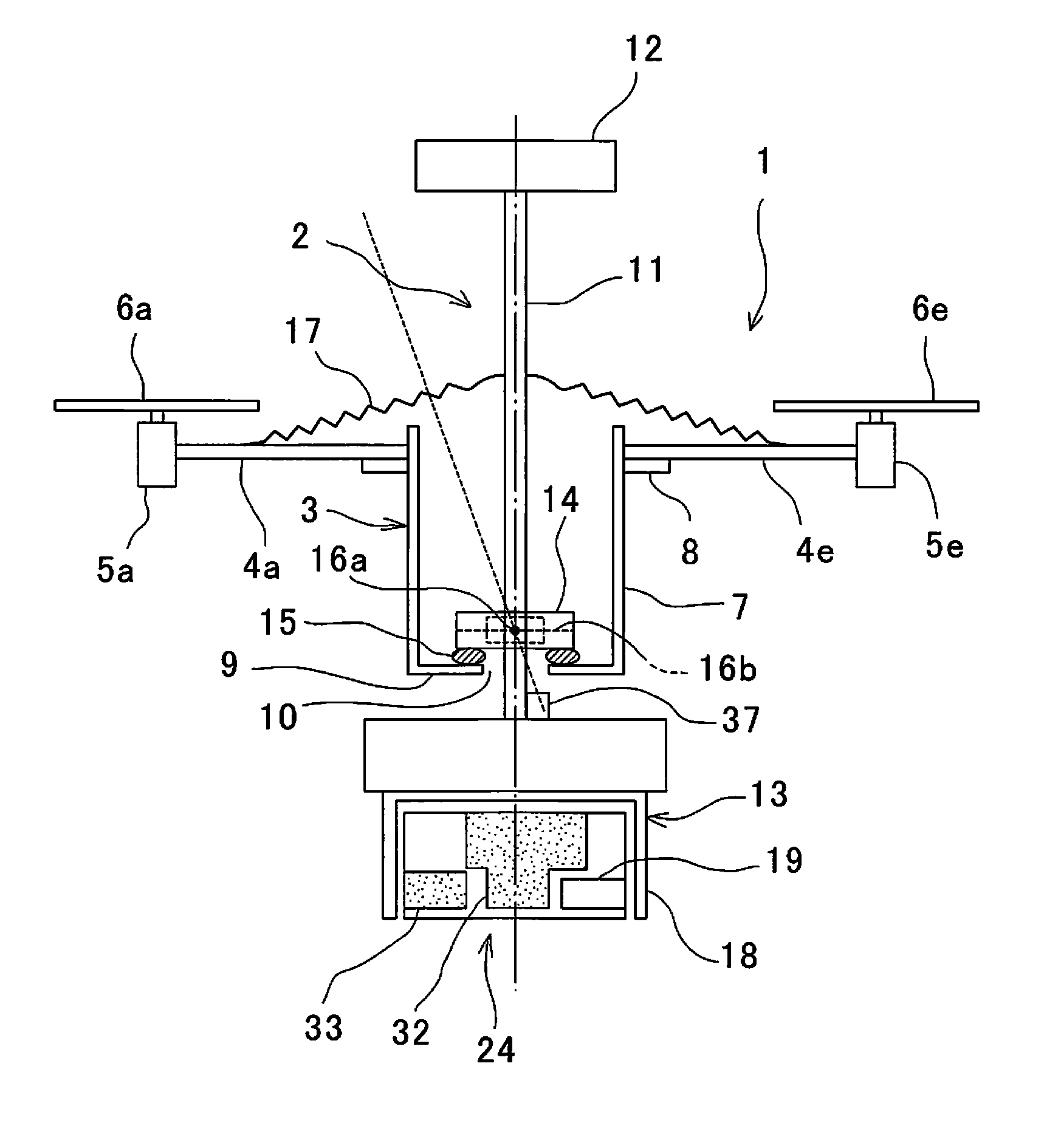
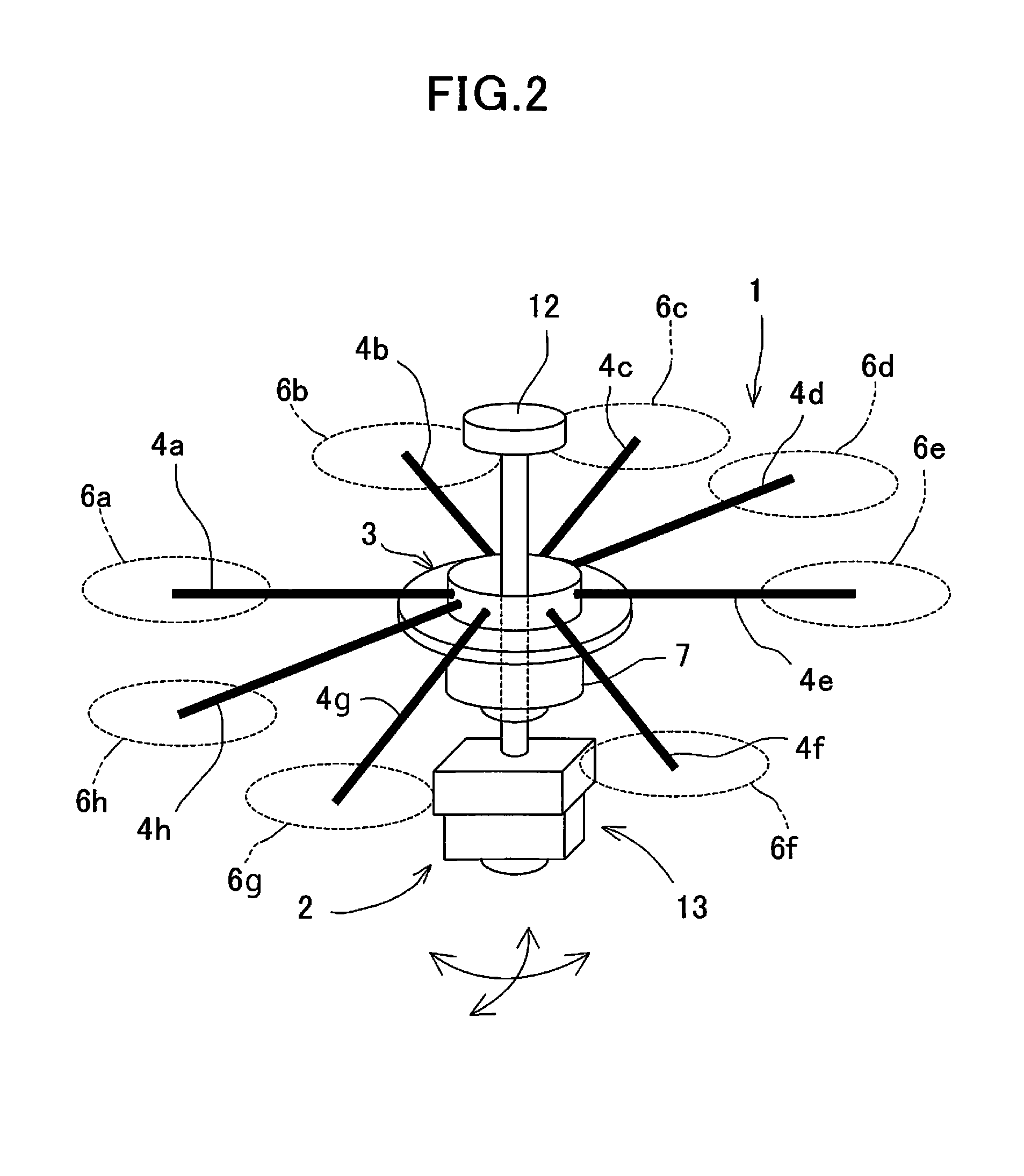
[0034]Description will be given below on an embodiment of the present invention by referring to the attached drawings.

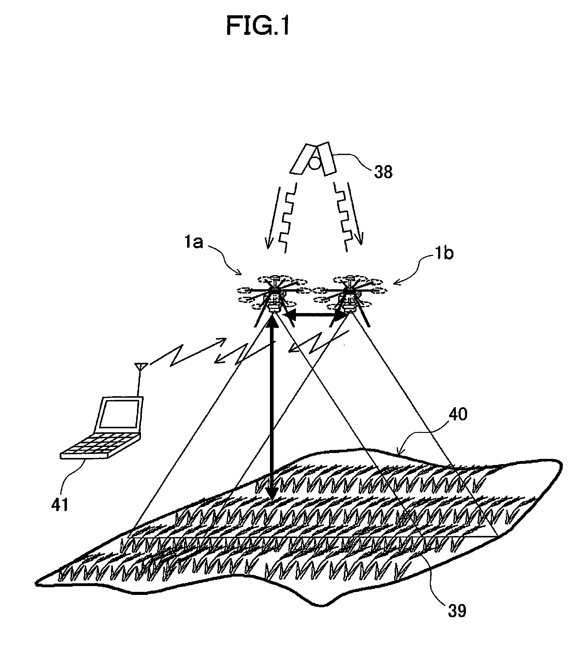
[0035]FIG. 1 shows a basic arrangement of an aerial photogrammetric system according to the present embodiment.

[0036]The aerial photogrammetric system primarily comprises two unmanned aerial vehicles (UAV's) 1a and 1b where cameras for photogrammetry are installed (hereinafter, it is referred as merely “UAV 1” if UAV 1a and UAV 1b is not distinguished from each other), and a base control device 41 installed on the ground surface. It is to be noted that, in the present embodiment, a small type helicopter is used as the UAV 1.

[0037]Further, in FIG. 1, reference numeral 38 represents a satellite, which issues a signal for position measurement to a GPS, and reference numeral 39 represents agricultural products, which are objects to be measured. Further, a range including the object to be measured 39 in a predetermined range is set as a range to be measured 40.

[0038]First...


PUM


Abstract

The invention provides aerial photogrammetry by using two or more flying vehicles, each equipped with a GPS device and an image pickup unit, comprising a step of setting up two or more photographing points and setting up a photographing point area, respectively, with each of the photographing points as the center, a step of measuring a position of the flying vehicle by the GPS device, a step where each of the flying vehicle reaches each corresponding photographing point area and maintains the position of the photographing point area, a step of acquiring a time when the flying vehicle finally reaches the photographing point area, a step of setting up a shutter timing time after a predetermined time from the moment when the flying vehicle has finally reached the photographing point area, and a step of taking aerial photographs by the two or more flying vehicles at the shutter timing time.

Description

BACKGROUND OF THE INVENTION[0001]The present invention relates to an aerial photogrammetry and an aerial photogrammetric system, using a small type flying vehicle equipped with a camera for photogrammetry on board.[0002]In recent years, with the progress of UAV (Unmanned Air Vehicle), a camera for photogrammetry is installed on UAV and aerial photogrammetry is performed by using the UAV.[0003]In a case where aerial photogrammetry is performed, photographs are taken while flying at an altitude as required at two points so that an object to be measured or a region to be measured is included, relative orientation is performed on images photographed at the two points, and photogrammetry is carried out by performing absolute orientation of the images based on known points (points having a geocentric coordinate already known).[0004]Normally, in aerial photogrammetry, an object and an object to be measured included in an image may be regarded as standstill objects. Therefore, in a case whe...

Claims


Application Information

Patent Timeline
Patent Type & Authority Applications(United States)
IPC IPC(8): G01C11/00
CPCG01C11/00G01C11/025A01B79/005G05D1/0094G05D1/104B64U10/13B64U2101/30
Inventor OHTOMO, FUMIOOTANI, HITOSHIOSARAGI, KAZUKIANAI, TETSUJI
Owner KK TOPCON
Why Eureka
Try Eureka