Actuation grip for a microsurgical instrument, and microsurgical instrument

a microsurgical instrument and actuation grip technology, applied in the field of microsurgical instruments, can solve the problems of reducing control precision, not entirely homogeneous transmission ratio, and greatly limited maximum possible transmission ratio, and achieves the effects of improving transmission ratio, less play, and more homogeneous transmission

Active Publication Date: 2014-05-01
KARL STORZ GMBH & CO KG
View PDF49 Cites 3 Cited by
  • Summary
  • Abstract
  • Description
  • Claims
  • Application Information

AI Technical Summary

Benefits of technology

[0006]Proceeding from this prior art, the object of the present invention is to provide a medical instrument of this kind with an actuation grip which offers an improved transmission ratio and more homogeneous transmission across the complete pivot range of the grip parts and which as far as possible has no parts of its mechanism lying open and has slight play.

Problems solved by technology

In a lever excursion by a fixed amount, a mechanism of this kind for converting a pivoting movement of the levers into an axial movement leads to a much greater axial excursion when the levers are positioned closely than when the levers are positioned wide open, and the maximum possible transmission ratio is greatly limited.
This mechanism too has a not entirely homogeneous transmission ratio, which reduces the control precision.
In addition, the maximum possible transmission ratio is relatively small, and the mechanism is expensive to produce and susceptible to production fluctuations.
The partially open mechanism is susceptible to contamination and, during an operation, can become jammed on a trocar sleeve or an incision opening, which greatly restricts the freedom of movement of the operating surgeon.

Method used


Image

  • Actuation grip for a microsurgical instrument, and microsurgical instrument
  • Actuation grip for a microsurgical instrument, and microsurgical instrument
  • Actuation grip for a microsurgical instrument, and microsurgical instrument

Examples


Embodiment Construction

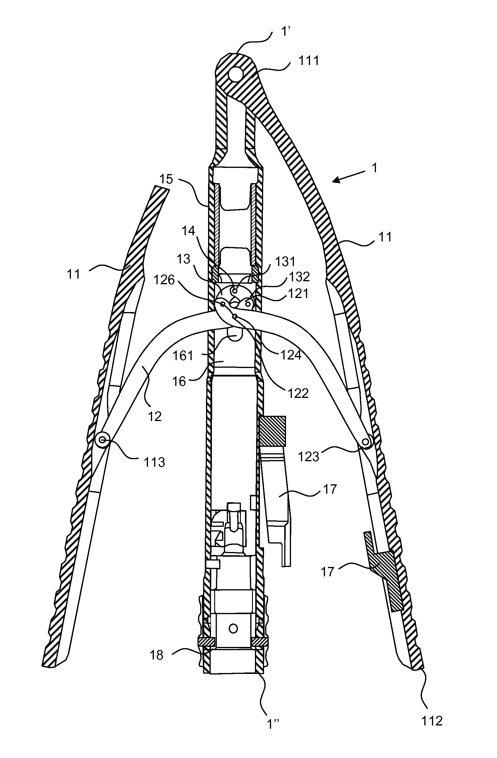
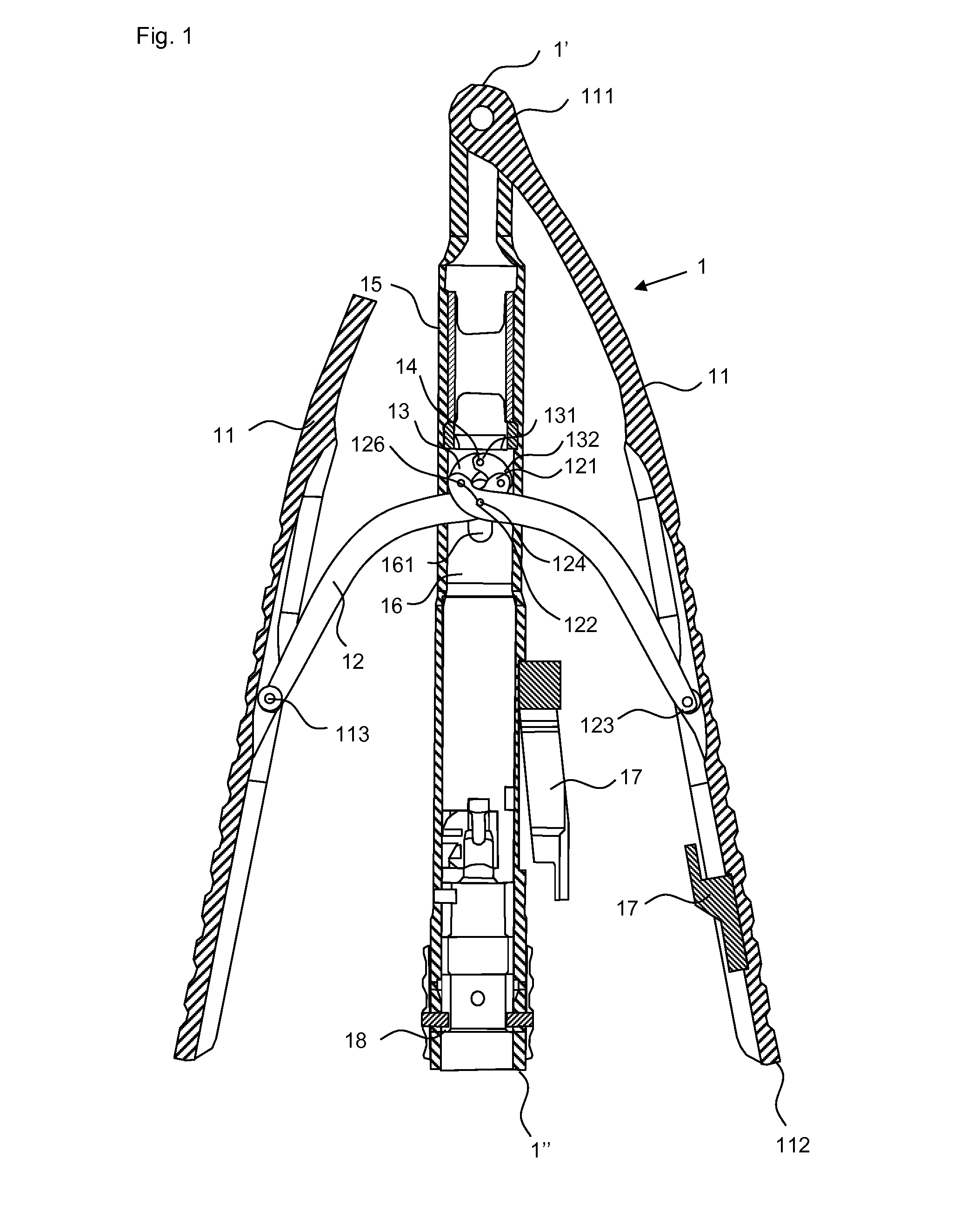
[0035]An actuation grip 1 according to the invention has two grip parts 11, which are coupled rotatably to the outer shank 15 at a common point located at their proximal end 111, as is shown in FIG. 1, the latter showing a longitudinal section in which the sectional plane contains the longitudinal axis of the shanks 15, 16. According to the invention, both grip parts 11 extend as far as the proximal end 1′ of the actuation grip 1, wherein one grip part 11 is shown sectioned on account of the position of the sectional plane. At an attachment point 113 located between the proximal end 111 and the distal end 112 of the grip parts 11, the latter are each rotatably coupled to a first long S-shaped lever 12, such that, with two grip parts 11, two first levers 12 are present which, at their ends 123 directed toward the grip parts 11, are coupled rotatably thereto. Between their ends 123 directed toward the grip parts 11 and their ends 121 directed away from the grip parts 11, the first lev...


PUM


Abstract

An actuation grip for a microsurgical instrument, with an inner shank, which is surrounded coaxially and cylindrically by an outer shank, wherein the shanks are axially movable relative to each other. Two pivotable grip parts, each with two ends, are coupled pivotably at a proximal end of the actuation grip. On each grip part, a first lever is articulated rotatably via an attachment point between the ends of the grip part, wherein the two first levers are coupled rotatably to each other at an intersection point between their ends. The first levers are each connected rotatably to a second lever at their ends directed away from the grip parts, such that the first levers form, with the second levers, a double scissor hinge which serves to move the two shanks axially relative to each other, in order to use this movement to actuate a surgical tool.

Description

FIELD OF THE INVENTION[0001]The invention relates to a microsurgical instrument for minimally invasive surgery and to an actuation grip for same.BACKGROUND OF THE INVENTION[0002]Microsurgical instruments for minimally invasive surgery have to meet particular demands specifically as regards a high degree of precision and the ability to control them ergonomically (i.e. with optimized control forces and kinematics) and using one hand. Minimally invasive surgery is increasingly being used for interventions which hitherto required opening the body of the patient at the appropriate locations, since with this surgery it is possible largely to avoid the negative effects of trauma.[0003]The prior art discloses the use of microsurgical instruments in microsurgery, e.g. in endoscopic cardiovascular surgery. These microsurgical instruments comprise a tool which is arranged distally on a guide shank and which is in most cases composed of two jaws, of which at least one is movable, and an actuati...

Claims


Application Information

Patent Timeline
Patent Type & Authority Applications(United States)
IPC IPC(8): A61B17/29A61B17/28A61B17/3201
CPCA61B2017/0046A61B2017/2919A61B2017/292A61B17/3201A61B17/2812A61B17/2909A61B2017/305A61B2017/2946A61B2017/2912
Inventor STEFAN, JOCHEN
Owner KARL STORZ GMBH & CO KG
Why Eureka
Try Eureka