
Centralized Computing

Active Publication Date: 2014-05-01
GRIDCORE
View PDF12 Cites 11 Cited by
  • Summary
  • Abstract
  • Description
  • Claims
  • Application Information

AI Technical Summary

Benefits of technology

The invention aims to solve problems by providing an efficient way for engineering teams to access a centralized computing centre. It also allows for scheduling a large number of remote desktops onto the resources of the centralized computing centre. Compared to the conventional system, the invention provides a more dynamic system layout and optimizes scheduling and computing capacity utilization, resulting in improved efficiency and less vulnerability to high latency.

Problems solved by technology

However, although bandwidth can generally be increased almost infinitively, there is a problem of high latency over long distance connections.
This problem is difficult to completely eliminate with current networking technology.
With engineering teams of a single organization spread across the globe, and high-end graphics demand of today's CAE applications, it is becoming increasingly difficult to sustain satisfactory performance of such centralized data and computing centres.
This is an inflexible design, lending little possibility to optimize the scheduling of desktop applications.
Further, the centralized computing resources (cluster nodes) in a cluster) are generally heterogeneous, catering to different needs for different applications.
Obviously, the more users that access the same computing centre, the more difficult it gets to share the scarce resources (e.g. graphics capable computers) between them in an efficient manner.
For example, it becomes increasingly difficult to optimally utilize the centralized computing resources.
Although engineers would like to use the idling resources, high latencies and practicalities involved with submitting a job, prevent them from doing this.

Method used


Image

  • Centralized Computing
  • Centralized Computing
  • Centralized Computing

Examples


Embodiment Construction

System Layout

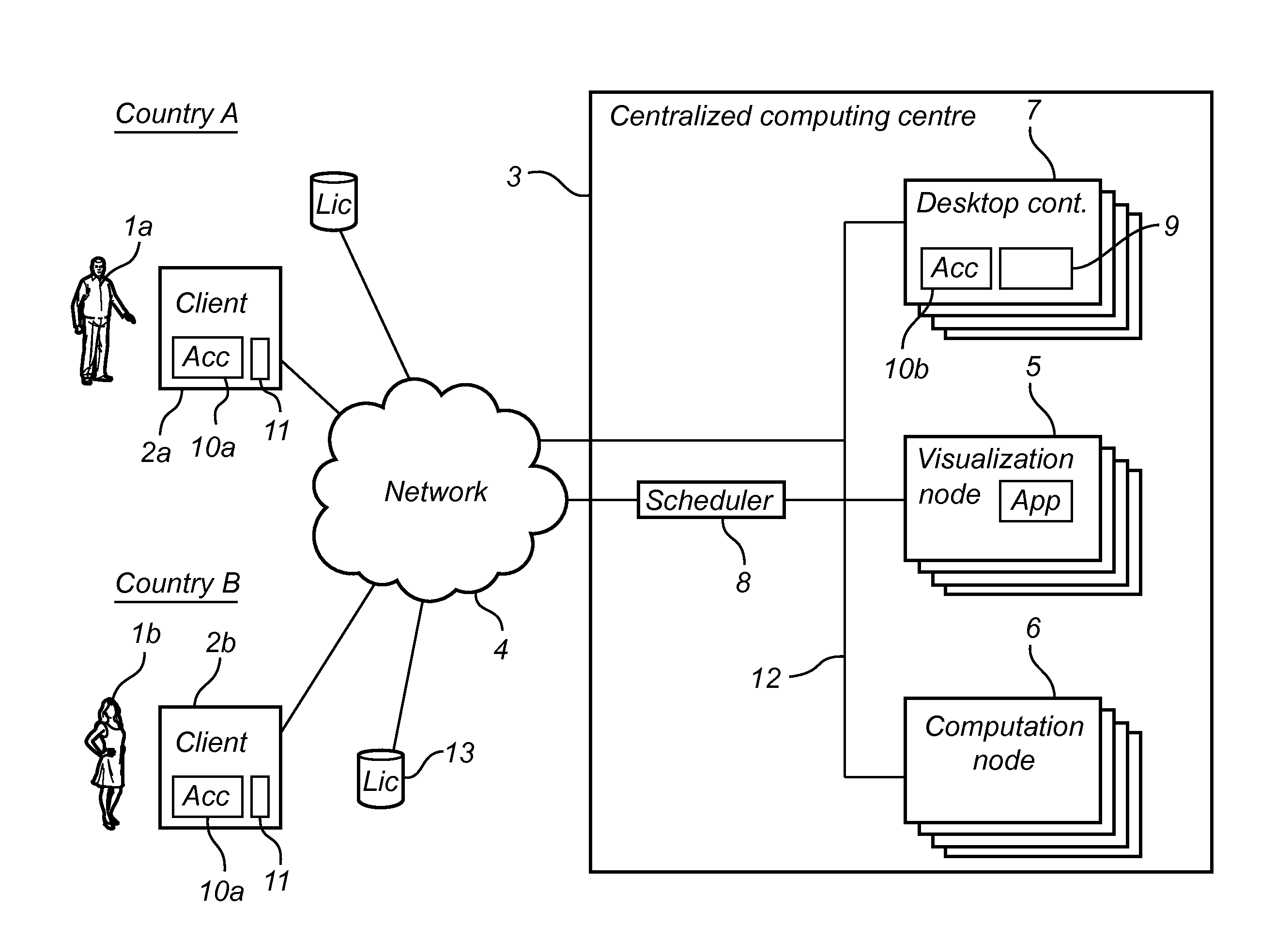
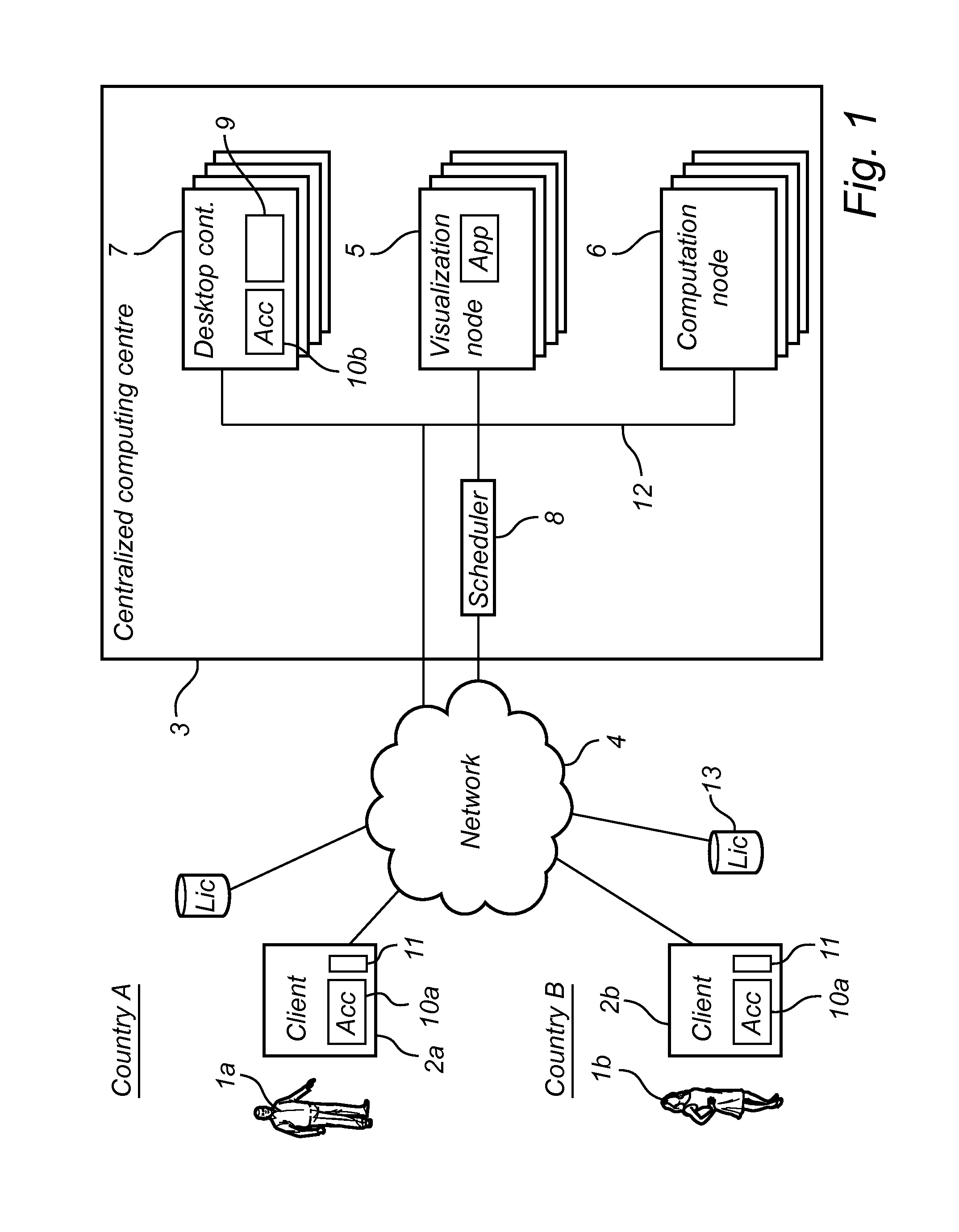
[0026]The centralized computing system illustrated in FIG. 1 includes two users 1a, 1b, located in different geographic locations, here different countries A and B, and using clients 2a, 2b to access a centralized computing centre 3 (here referred to as a High Performance Computing (HPC) centre) over a network 4. Of course, the number of users is typically significantly greater than two, but is here limited for reasons of simplicity and clarity.

[0027]The clients 2a, 2b are typically so called “thin” client, indicating that they do not have any significant processing power, and they can thus be any standard computer such as a portable laptop or even tablet computer. However, the client may of course also be a more powerful computer. The clients are adapted to allow their users remote visual access to resources in the HPC centre by a remote desktop. Using the remote desktop, the user may submit to the HPC centre computing jobs requiring high performance computing resource...


PUM


Abstract

A centralized computing system, comprising a centralized computing centre comprising a plurality of nodes, a plurality of clients in different geographical regions, an IP network interconnecting the clients and the centralized computing centre, and a scheduler scheduling jobs onto suitable nodes.The plurality of nodes include desktop container nodes, exclusively used for running remote desktop server software, each remote desktop server software communicating visual output to a remote desktop viewer on one of the clients. The system further comprises an accelerator arrangement capable of providing communication of visual output between the desktop container nodes and the clients using an alternative transport layer protocol other than transmission control protocol (TCP), the alternative transport layer protocol being more efficient than TCP over a high-latency connection.

Description

FIELD[0001]The present invention relates to a centralized computing, and more specifically to a system with a centralized computing centre having a plurality of nodes, a plurality of clients, an IP network interconnecting the clients and the centralized computing centre, and a scheduler scheduling jobs from the clients onto suitable nodes.BACKGROUND[0002]In many computing tasks requiring significant computing power, such as complex calculations or graphical simulations, there is a need to use computer clusters including many computers. The Internet and constantly improved bandwidth has made it possible to access such computer clusters, sometimes referred to as computing centres, remotely, and there is thus a desire to centralize such computing centres, and to locate them where the associated costs are low. Ideal locations should have e.g. a cool climate (requiring less cooling), affordable electricity prices, and low rent. Another advantage of centralizing the computing centres is t...

Claims


Application Information

Patent Timeline
IPC IPC(8): G06F15/16
CPCG06F9/4843H04L67/08H04L67/10H04L69/326G06F9/5072H04L41/5096
Inventor SUBRAMANIAN, DEVARAJAN
Owner GRIDCORE
Learn More