Tiled cache invalidation

a cache and tile technology, applied in static indicating devices, memory adressing/allocation/relocation, instruments, etc., can solve the problems of incorrect data being invalidated, unfavorable use of memory bandwidth and power, and difficulty in cache invalidation, so as to reduce the amount of memory bandwidth utilization

Active Publication Date: 2014-05-01
NVIDIA CORP
View PDF2 Cites 15 Cited by
  • Summary
  • Abstract
  • Description
  • Claims
  • Application Information

AI Technical Summary

Benefits of technology

[0012]One advantage of the disclosed techniques is that cache entries storing data that do not need to be written out to memory are invalidated in a graphics subsystem that implements a cache tiling architecture. An additional advantage is that cache entries are invalidated in an architecture that includes multiple parallel processing entities. A further advantage is that by including a cache invalidate command in multiple cache tile batches, the invalidate command can be applied on a per-cache-tile basis, which allows data associated with each cache tile to be invalidated as the data is processed, thereby reducing the amount of memory bandwidth utilization incurred due to writing out the data out to memory.

Problems solved by technology

One challenging aspect of processing data in this manner is managing data flow between the cache memory that stores the cache tiles and an external memory such as a frame buffer.
Some intermediate data is only needed during a short processing interval and does not need to be written out from the cache memory to the frame buffer, which would unnecessarily consume memory bandwidth and power.
In a graphics subsystem that implements a tiling architecture, cache invalidation is not straightforward.
However, if no mechanism exists to account for this discrepancy, or if the wrong time to execute the cache invalidate command is chosen, then there is a risk that the cache invalidate command is executed at a point in time that results in the wrong data being invalidated.
Managing this risk is further complicated in a highly parallel tiling architecture that includes multiple processing entities.

Method used


Image

  • Tiled cache invalidation
  • Tiled cache invalidation
  • Tiled cache invalidation

Examples


Embodiment Construction

[0025]In the following description, numerous specific details are set forth to provide a more thorough understanding of the present invention. However, it will be apparent to one of skill in the art that the present invention may be practiced without one or more of these specific details.

System Overview

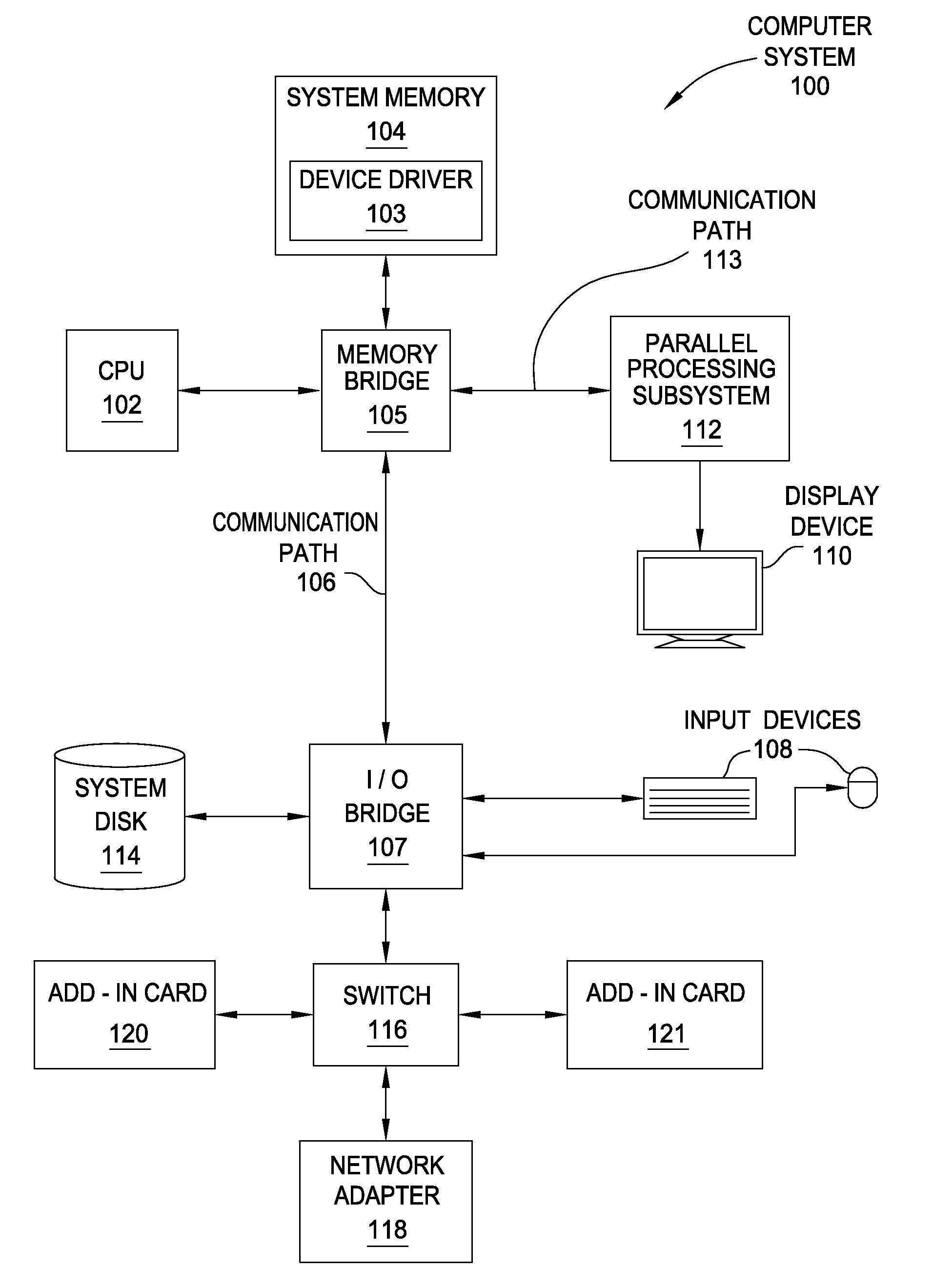
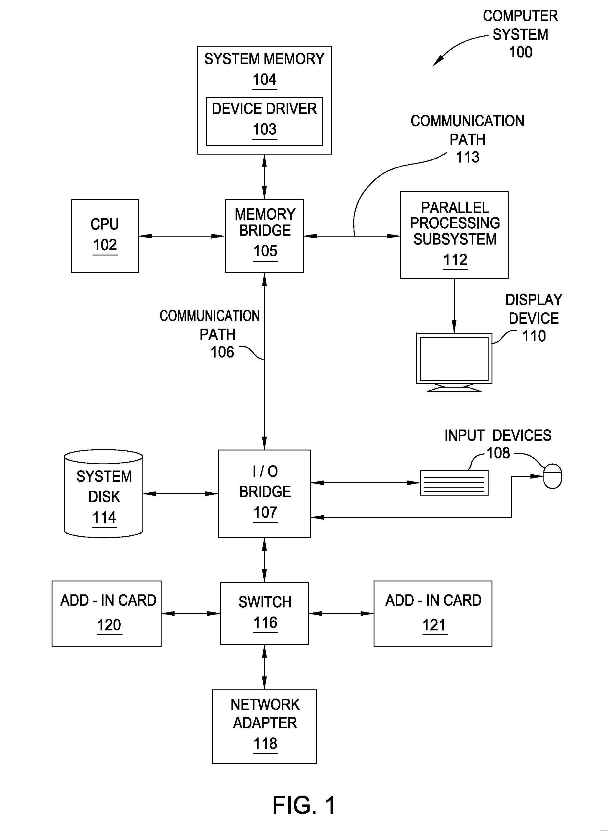
[0026]FIG. 1 is a block diagram illustrating a computer system 100 configured to implement one or more aspects of the present invention. As shown, computer system 100 includes, without limitation, a central processing unit (CPU) 102 and a system memory 104 coupled to a parallel processing subsystem 112 via a memory bridge 105 and a communication path 113. Memory bridge 105 is further coupled to an I / O (input / output) bridge 107 via a communication path 106, and I / O bridge 107 is, in turn, coupled to a switch 116.

[0027]In operation, I / O bridge 107 is configured to receive user input information from input devices 108, such as a keyboard or a mouse, and forward the input information to C...


PUM


Abstract

One embodiment of the present invention sets forth a graphics subsystem. The graphics subsystem includes a first tiling unit associated with a first set of raster tiles and a crossbar unit. The crossbar unit is configured to transmit a first set of primitives to the first tiling unit and to transmit a first cache invalidate command to the first tiling unit. The first tiling unit is configured to determine that a second bounding box associated with primitives included in the first set of primitives overlaps a first cache tile and that the first bounding box overlaps the first cache tile. The first tiling unit is further configured to transmit the primitives and the first cache invalidate command to a first screen-space pipeline associated with the first tiling unit for processing. The screen-space pipeline processes the cache invalidate command to invalidate cache lines specified by the cache invalidate command.

Description

CROSS-REFERENCE TO RELATED APPLICATIONS[0001]This application claims benefit of U.S. provisional patent application Ser. No. 61 / 719,271, filed Oct. 26, 2012 and titled “An Approach for Tiled Caching.” The subject matter of this related application is hereby incorporated herein by reference.BACKGROUND OF THE INVENTION[0002]1. Field of the Invention[0003]Embodiments of the present invention relate generally to three-dimensional (3D) graphics processing and, more particularly, to tiled cache invalidation.[0004]2. Description of the Related Art[0005]Some graphics subsystems implement a tiling architecture in which a render target is divided into partitions referred to as tiles. Some tiling systems also store data in an on-chip cache memory during rendering, which increases performance and reduces memory bandwidth consumption. For improved performance, multiple processing entities may be provided to process the tiles in parallel.[0006]One challenging aspect of processing data in this man...

Claims


Application Information

Patent Timeline
Patent Type & Authority Applications(United States)
IPC IPC(8): G06F12/08
CPCG06F12/0808G06F12/0875G06F2212/302G06T15/005G06T1/60Y02D10/00G06T15/405G06F9/38G06T1/20G09G5/395G09G5/003G06T15/503G06F9/44G06T15/80G06T17/20
Inventor HAKURA, ZIYAD S.KILGARIFF, EMMETT M.
Owner NVIDIA CORP
Why Eureka
Try Eureka