
Robot using multi-output differential gear

a technology of differential gear and robot, which is applied in the direction of arms, manufacturing tools, gears, etc., can solve the problems of small and large plumbing related accidents, large inspection and replacement difficulty, and constant wear of plumbing facilities

Active Publication Date: 2014-05-08
RES & BUSINESS FOUND SUNGKYUNKWAN UNIV
View PDF8 Cites 28 Cited by
  • Summary
  • Abstract
  • Description
  • Claims
  • Application Information

AI Technical Summary

Benefits of technology

This patent aims to provide a robot that can drive stable even when its movement paths change. It uses a special gear system called a multi-output differential gear. This allows the robot to maintain its balance and stability during movement.

Problems solved by technology

However, these plumbing facilities are mostly buried underground, and thus there is much difficulty in inspecting and replacing them when the inner walls are corroded after a certain period of time or damaged by external environmental conditions.
As such, plumbing facilities are continuously wearing out, and various defects that occur in this process are causing small and large plumbing related accidents every year.
However, insufficient manpower and technology makes it difficult to conduct systematic and regular inspections on the plumbing facilities.
However, conventional robots had to be equipped with a driver (actuator) for every wheel to adjust the movement state of each wheel separately according to the shape of the plumbing, thereby increasing the size of the robots.

Method used


Image

  • Robot using multi-output differential gear
  • Robot using multi-output differential gear
  • Robot using multi-output differential gear

Examples


exemplary embodiment 100

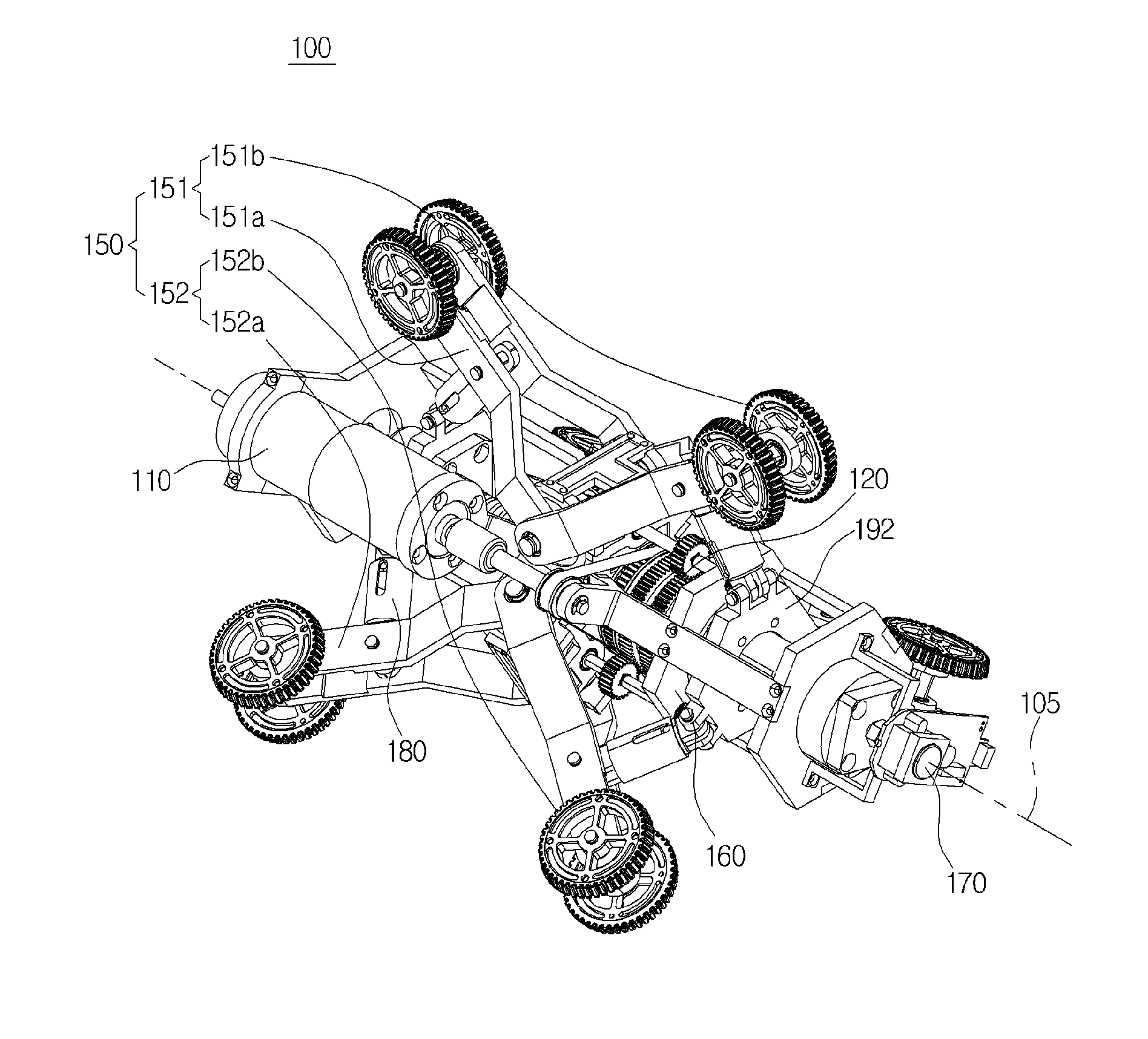
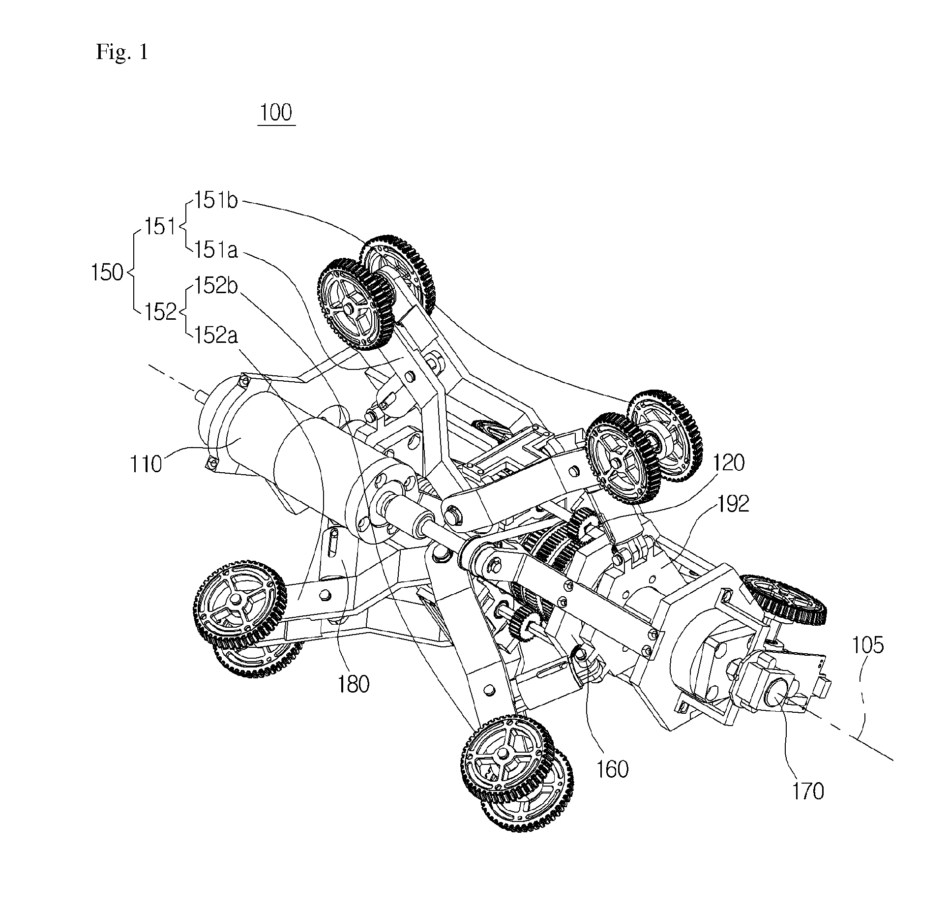
[0085]Hereinbelow is explanation on an operation of a robot using such a multi-output differential gear mentioned above according to a first exemplary embodiment 100.

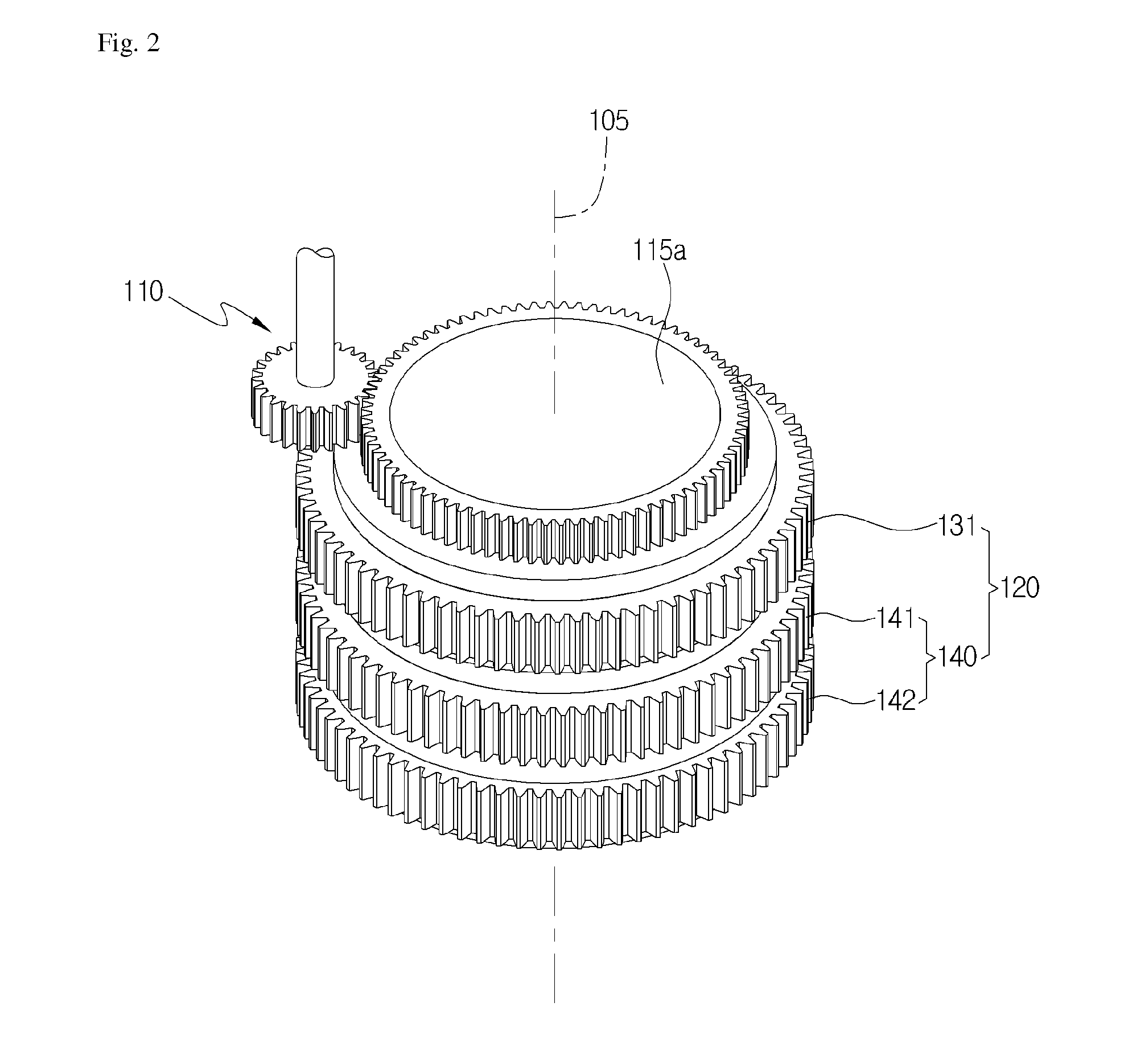
[0086]First of all, hereinbelow is explanation on an operation of the differential gear 120, where a driving power and external resistance is received, a differentiation is made, and the differentiated output value is transmitted to the motion section 150.

[0087]First of all, hereinbelow is explanation on an operation of the first differential gear 130. In the case where an external resistance is not transmitted from the first motion section 151 to the first output gear 131, the driving power transmitted from the driver 110 is transmitted to the first epicyclic gear 132 by the drive transmitter 115a, 115b, and the first epicyclic gear 132 rotates the first output gear 131 in the same rotation direction as that of the driver 110 as it rotates along the outer circumference of the middle gear 133. Herein, the rotary speed d...

exemplary embodiment 200

[0111]According to the second exemplary embodiment 200 of the present disclosure, the four motion sections 251, 252, 253, 254 are disposed, but are not limited to, such that each of them is distanced by 90° from one another around the central axis 105 of the differential gear 220. Meanwhile, regarding the motion sections, everything is the same as in each motion section 150 of the first exemplary embodiment besides the disposition relationship, and thus further detailed explanation is omitted.

[0112]There are provided four buffering sections 280 so as to correspond to the four motion sections, but beside this, everything regarding the buffering section is the same as in the first exemplary embodiment 100, and thus further detailed explanation is omitted

[0113]Regarding the overall shape of a robot using a multi-output differential gear, compared to the first exemplary embodiment 100, in the second exemplary embodiment 200, the differential gear 220 has four output gears, and thus ther...


PUM


Abstract

Provided herein is a robot using a multi-output differential gear, the robot comprising a driver; a differential gear configured to receive a driving power from the driver, and to drive in an interlocked manner with the driving power to generate at least three outputs differentiated from the driving power; and a motion section configured to drive in an interlocked manner with an output generated from the differential gear, and to apply an external resistance to the differential gear.

Description

CROSS-REFERENCE TO RELATED APPLICATION[0001]This application claims the benefit of priority under 35 U.S.C. §119(a) of Korean Patent Application No. 10-2012-0119369, filed on Oct. 26, 2012, in the Korean Intellectual Property Office, the entire disclosure of which is incorporated herein by reference for all purposes.BACKGROUND[0002]1. Field[0003]The following description relates to a robot using a multi-output differential gear, for example, a robot using a multi-output differential gear capable of generating a plurality of outputs using one driver and of changing each output flexibly according to changes in movement paths.[0004]2. Description of Related Art[0005]Plumbing facilities are one of various infrastructures in industries, and are being established as supply routes for various energy resources as they are being distributed here and there nationwide like blood vessels in a human body. However, these plumbing facilities are mostly buried underground, and thus there is much di...

Claims


Application Information

Patent Timeline
IPC IPC(8): F16H37/06
CPCY10S901/25F16H37/065F16H3/721Y10T74/20317F16L55/30B25J5/00F16L55/32B60K17/16F16H37/08F16H48/10
Inventor CHOI, HYOUK RYEOLKIM, HOMOONSUH, JUNG SEOKCHOI, YUN SEOK
Owner RES & BUSINESS FOUND SUNGKYUNKWAN UNIV
Learn More