Cooler and motor-integrated power conversion apparatus

Active Publication Date: 2014-05-08
MITSUBISHI ELECTRIC CORP
View PDF7 Cites 4 Cited by
  • Summary
  • Abstract
  • Description
  • Claims
  • Application Information

AI Technical Summary

Benefits of technology

The cooler in this patent helps to avoid pressure loss and provides better cooling performance. It simplifies the cooling system by using a single coolant circuit. The motor-integrated power conversion apparatus is smaller and more compact, with a high-density cooler integrated into the electric motor bracket and motor. This leads to improved cooling performance.

Problems solved by technology

Therefore, it is inevitable that the flow path length becomes long and large pressure loss occurs.
In this case, there is a problem that an external pump with a high performance is needed in order to improve the cooling performance.
In addition, in the conventional example shown in Patent Document 3, a plurality of entrances and exits for causing cooling media to flow in opposite directions need to be formed in the cooling plate, and therefore there is a problem that the arrangement of cooling medium pipes is complicated.
In addition, due to the entrances and exits provided at a plurality of positions, there is a problem that a plurality of external pumps also need to be prepared.
Thus, in any of Patent Documents 1 to 3, there is a problem that the size of the cooler system including external pumps is large and its cost is high.

Method used


Image

  • Cooler and motor-integrated power conversion apparatus
  • Cooler and motor-integrated power conversion apparatus
  • Cooler and motor-integrated power conversion apparatus

Examples


embodiment 1

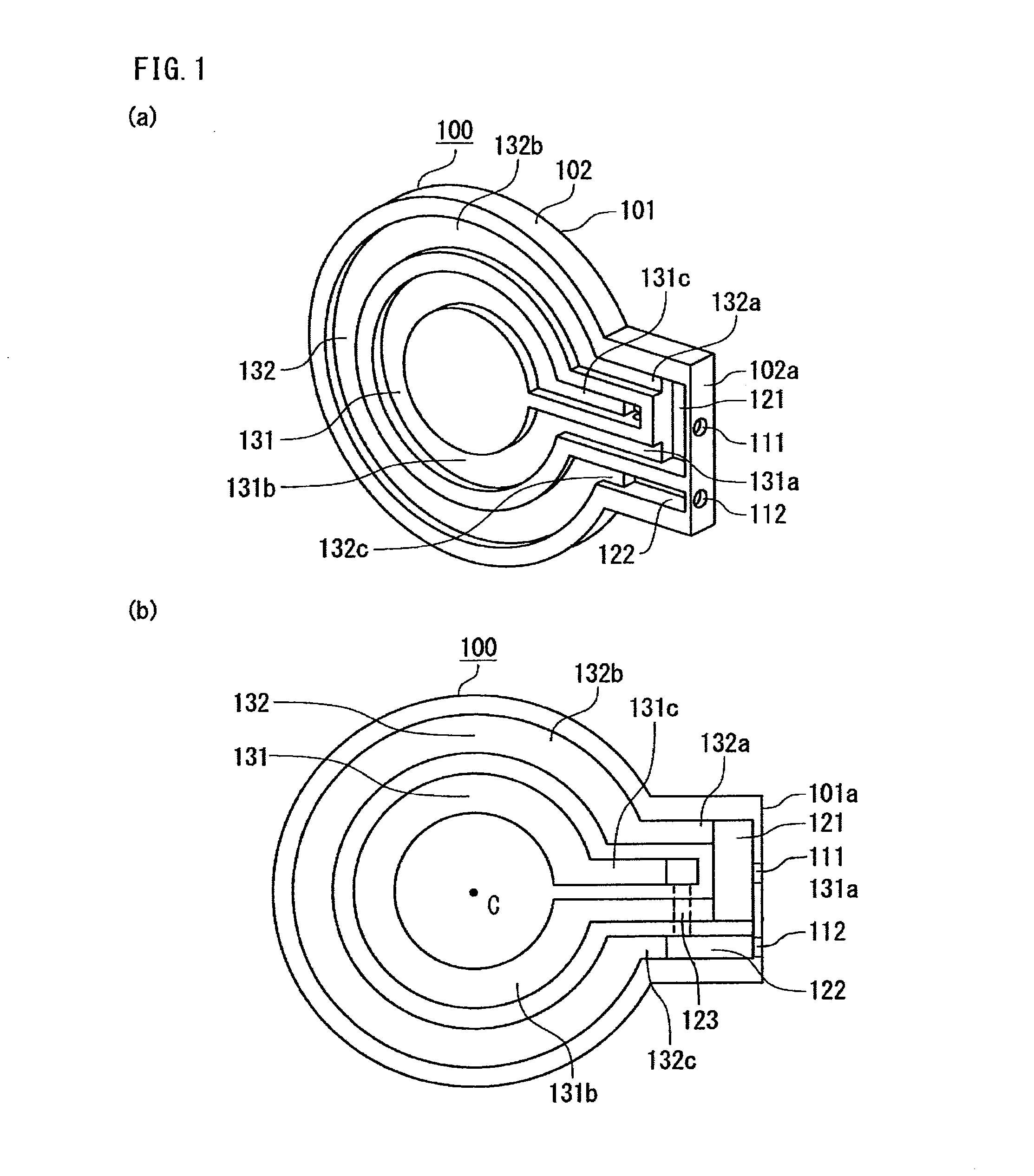
[0025]FIGS. 1(a) and 1(b) are a perspective view and a front view showing embodiment 1 of a cooler according to the present invention. A cooler 100 according to the present invention includes a cooler base body having a predetermined thickness and a planar shape, a surface thereof serving as a cooling surface. FIG. 1 is a diagram showing the configuration of a flow path formed inside the cooler base body, through which a cooling medium flows. As shown in FIG. 1, a cooling medium entrance 111 and a cooling medium exit 112 are formed which open on one end surface 102a which is an outer side surface of the cooler 100. On the same plane opposite to a cooling surface 101 of a plate 102, a first cooling medium flow path 131 and a second cooling medium flow path 132 through which cooling media flow are formed concentrically around a central axis C. Between the cooling medium entrance 111 and ends of the first cooling medium flow path 131 and the second cooling medium flow path 132, a cooli...

embodiment 2

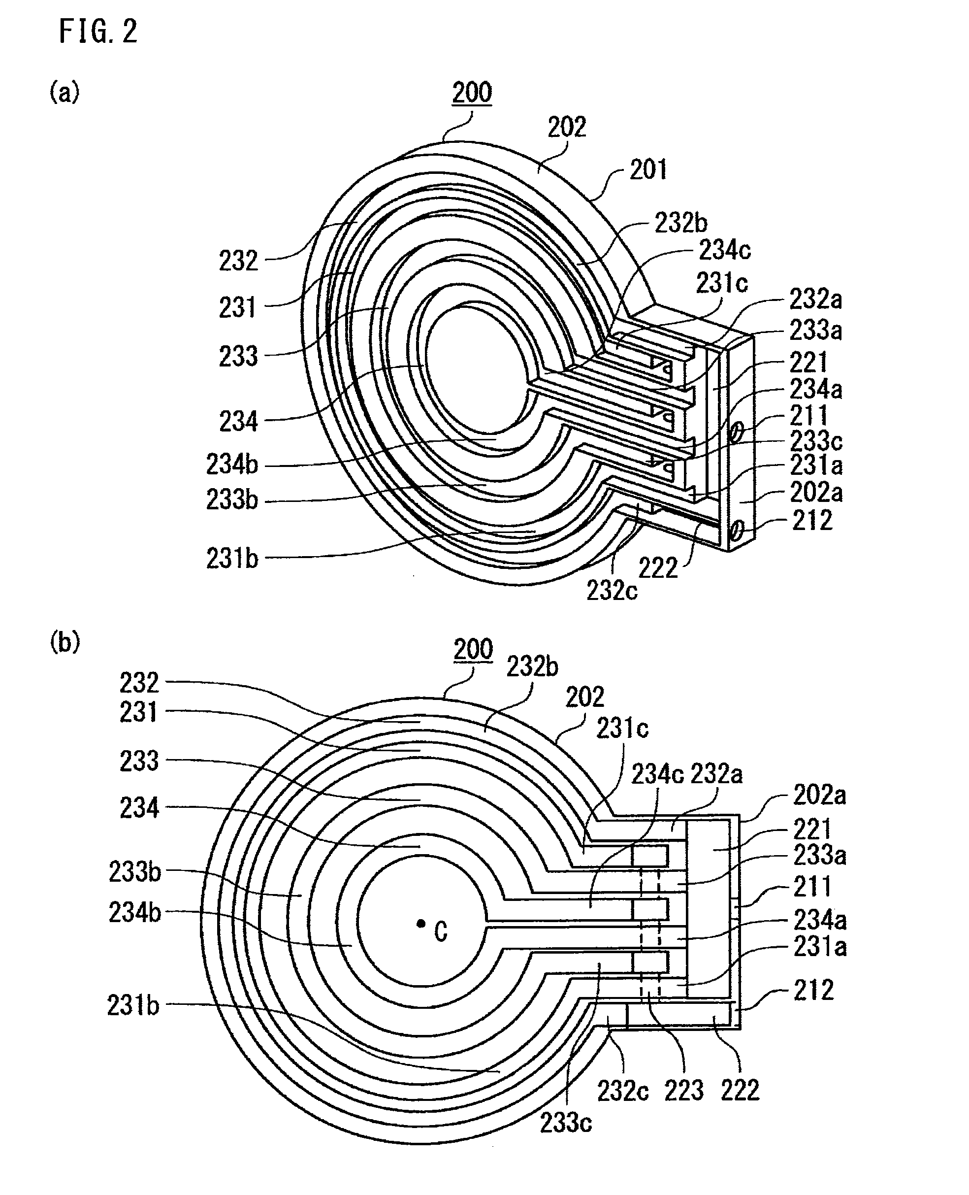
[0033]FIGS. 2(a) and 2(b) are a perspective view and a front view showing embodiment 2 of a cooler according to the present invention, and showing the configuration of a flow path through which a cooling medium flows. As shown in FIG. 2, a pair of a cooling medium entrance 211 and a cooling medium exit 212 are formed on one end surface 202a which is an outer side surface of a cooler base body of a cooler 200. On the same plane opposite to a cooling surface 201 of a plate 202, a first cooling medium flow path 231, a second cooling medium flow path 232, a third cooling medium flow path 233, and a fourth cooling medium flow path 234 through which cooling media flow are formed concentrically around a central axis C. Between the cooling medium entrance 211 and ends of the first cooling medium flow path 231 to the fourth cooling medium flow path 234, a cooling medium branch path 221 is formed for dividing a cooling medium flowing from the cooling medium entrance 211, to cause the divided ...

embodiment 3

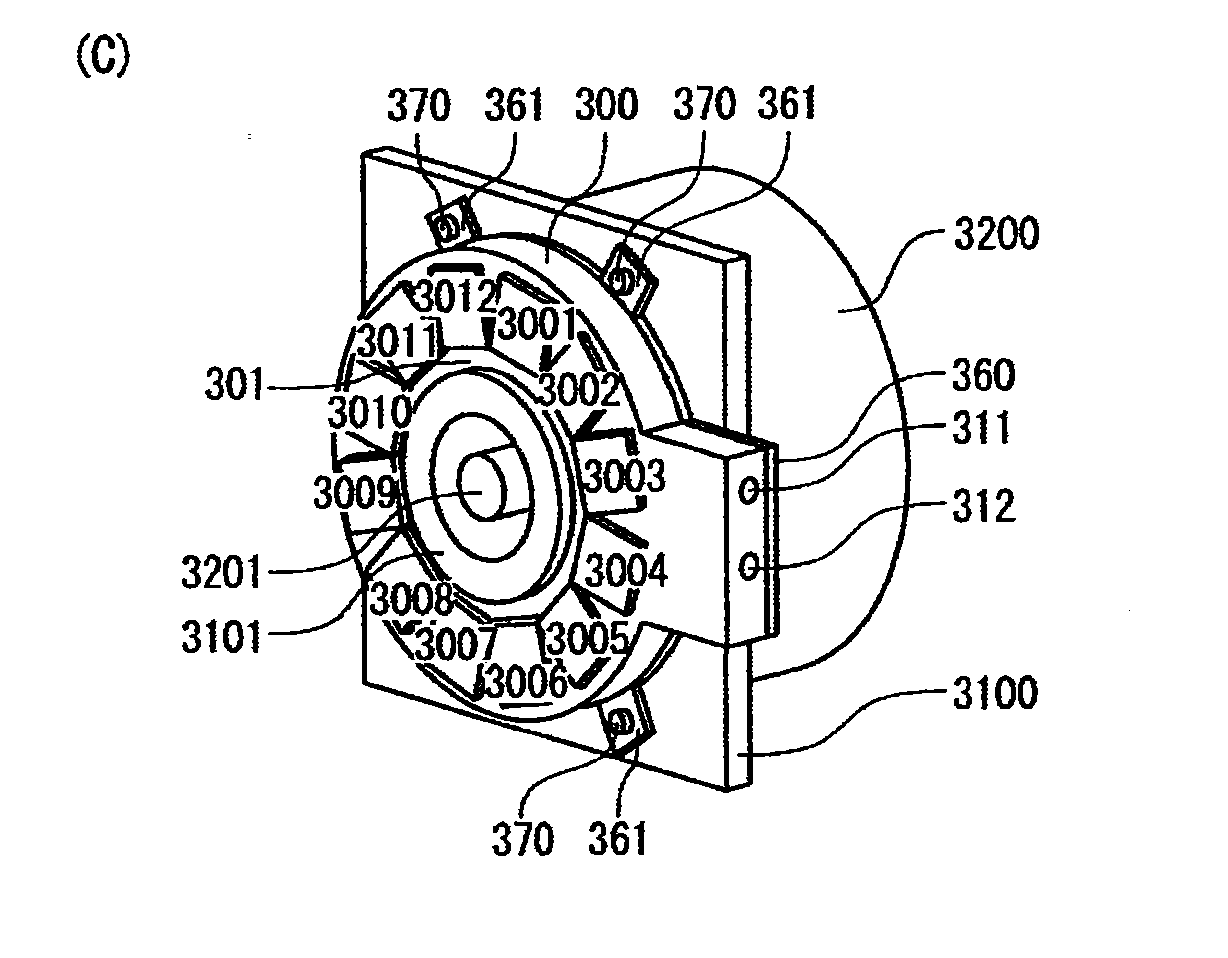
[0045]FIG. 3 is a diagram showing a motor-integrated power conversion apparatus according to the present invention. Specifically, FIGS. 3(a) and 3(c) are perspective views and FIG. 3(b) is a front view. It is noted that in FIG. 3(c), a cooler 300, an electric motor bracket 3100, and an electric motor 3200 are drawn such that the cooling surface 301 faces to the front side.

[0046]As shown in FIG. 3, the cooler 300 is almost the same as that shown in the above embodiment 1, as an example.

[0047]A difference from the above embodiment 1 is that a through hole 350 through which an electric motor shaft 3201 penetrates is formed on the central axis of arcs of a first cooling medium flow path 331 and a second cooling medium flow path 332 of the cooler 300, and power conversion semiconductor devices or power conversion semiconductor modules 3001 to 3012 for controlling the electric motor 3200 are fixed on the cooling surface 301.

[0048]As shown in FIG. 3(c), the motor-integrated power conversio...


PUM


Abstract

A surface of a plate (102) having a predetermined thickness is used as a cooling surface (101). A pair of cooling medium entrance and exit (111, 112) are provided on one end surface (102a). First and second cooling medium flow paths (131, 132), a cooling medium branch path (121) communicating with the cooling medium entrance (111) and used for dividing cooling medium to flow into the cooling medium flow paths (131, 132), and a cooling medium merging path (122) at which the cooling media flowing from the exits of the cooling medium flow paths (131, 132) merge, are formed on a surface opposite to the cooling surface (101). The cooling medium flowing clockwise through the first cooling medium flow path (131) passes through a cooling medium communicating flow path (123) formed so as to three-dimensionally cross the first cooling medium flow path (131), so that the cooling medium flowing counterclockwise through the second cooling medium flow path (132) and the cooling medium flowing through the first cooling medium flow path (131) flow into the cooling medium merging path (122). Thus, pressure loss is avoided, high cooling performance is obtained, and simplification of a cooling system including a cooling medium pipe and the like can be realized.

Description

TECHNICAL FIELD[0001]The present invention relates to a cooler and a motor-integrated power conversion apparatus including the cooler, and particularly, to a cooler for performing cooling by a liquid as a cooling medium, e.g., water, flowing inside the cooler, and a motor-integrated power conversion apparatus using the cooler.BACKGROUND ART[0002]In a power conversion semiconductor device or a power conversion semiconductor module, large thermal loss occurs upon current application. Therefore, as a cooler, a liquid-cooling-type cooler is used which forcibly causes a cooling medium to flow from the outside, and various patterns of the cooling flow path are disclosed.[0003]For example, a cooler for semiconductor device shown in Patent Document 1 has a lower cooling unit having a forward path portion formed in a whorl shape from the entrance for cooling water to a central portion, and a return path portion adjacent to the forward path portion, returning from the forward path portion to ...

Claims


Application Information

Patent Timeline
IPC IPC(8): H02K9/00
CPCH02K9/005H02K9/00H05K7/20927H02K11/33H02K9/227H02M7/48
Inventor MUKUNOKI, YASUSHIGESUZUKI, TAKAHARUYAMAUCHI, HIDEHITO
Owner MITSUBISHI ELECTRIC CORP
Why Eureka
Try Eureka