Eureka AIR delivers breakthrough ideas for toughest innovation challenges, trusted by R&D personnel around the world.

Control device having a night light

Inactive Publication Date: 2014-05-08
LUTRON TECH CO LLC
View PDF9 Cites 16 Cited by
  • Summary
  • Abstract
  • Description
  • Claims
  • Application Information

AI Technical Summary

Benefits of technology

The present invention offers a night light for a control device, making it easy to find in dark spaces. The night light is powered by a low-power circuit and is battery-friendly with a long battery life. The night light comprises a lens that conducts the light from the night light circuit to the surface of the remote control and provides good off-angle viewing of the night light. The night light may also be provided on a button of the remote control, for example, the button that causes a lighting load to be illuminated upon actuation. The lens of the night light may be raised from the surface of the button to provide tactile feedback to assist a user in locating the button that causes the lighting load to be illuminated when the control device is being operated in the dark space.

Problems solved by technology

In addition, some prior art dimmer switches dimly backlit one or more of the actuators when the controlled lighting load was off.
However, if the dimmer switch is a “two-wire” device without a connection to the neutral side of the AC power source, the current required to illuminate the night light often needs to be conducted through the lighting load.
When the magnitude of the current conducted through the lighting loads is too great, the lighting loads may flicker or provide otherwise poor performance.
However, some of the wireless remote controls of the prior art lighting control systems were powered by batteries, which have limited lifetimes that are dependent upon the usage and the total current drawn from the batteries as well as how often the remote controls are used.
The prior art battery-powered remote controls did not provide night lights, and simply illuminated the visual indicators for a period of time after one of the buttons of the remote control was actuated.

Method used


Image

  • Control device having a night light
  • Control device having a night light
  • Control device having a night light

Examples


Embodiment Construction

[0050]The foregoing summary, as well as the following detailed description of the preferred embodiments, is better understood when read in conjunction with the appended drawings. For the purposes of illustrating the invention, there is shown in the drawings an embodiment that is presently preferred, in which like numerals represent similar parts throughout the several views of the drawings, it being understood, however, that the invention is not limited to the specific methods and instrumentalities disclosed.

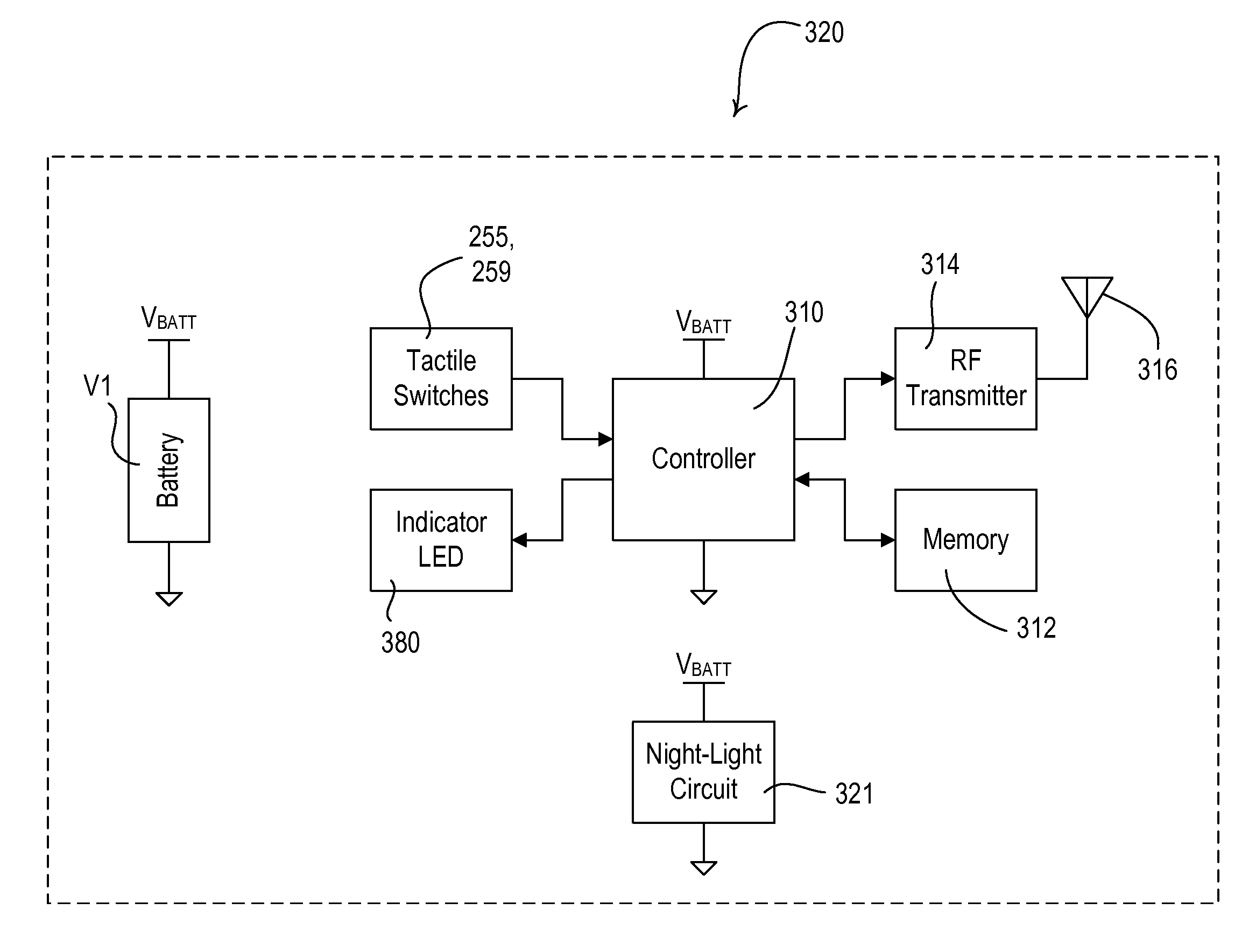
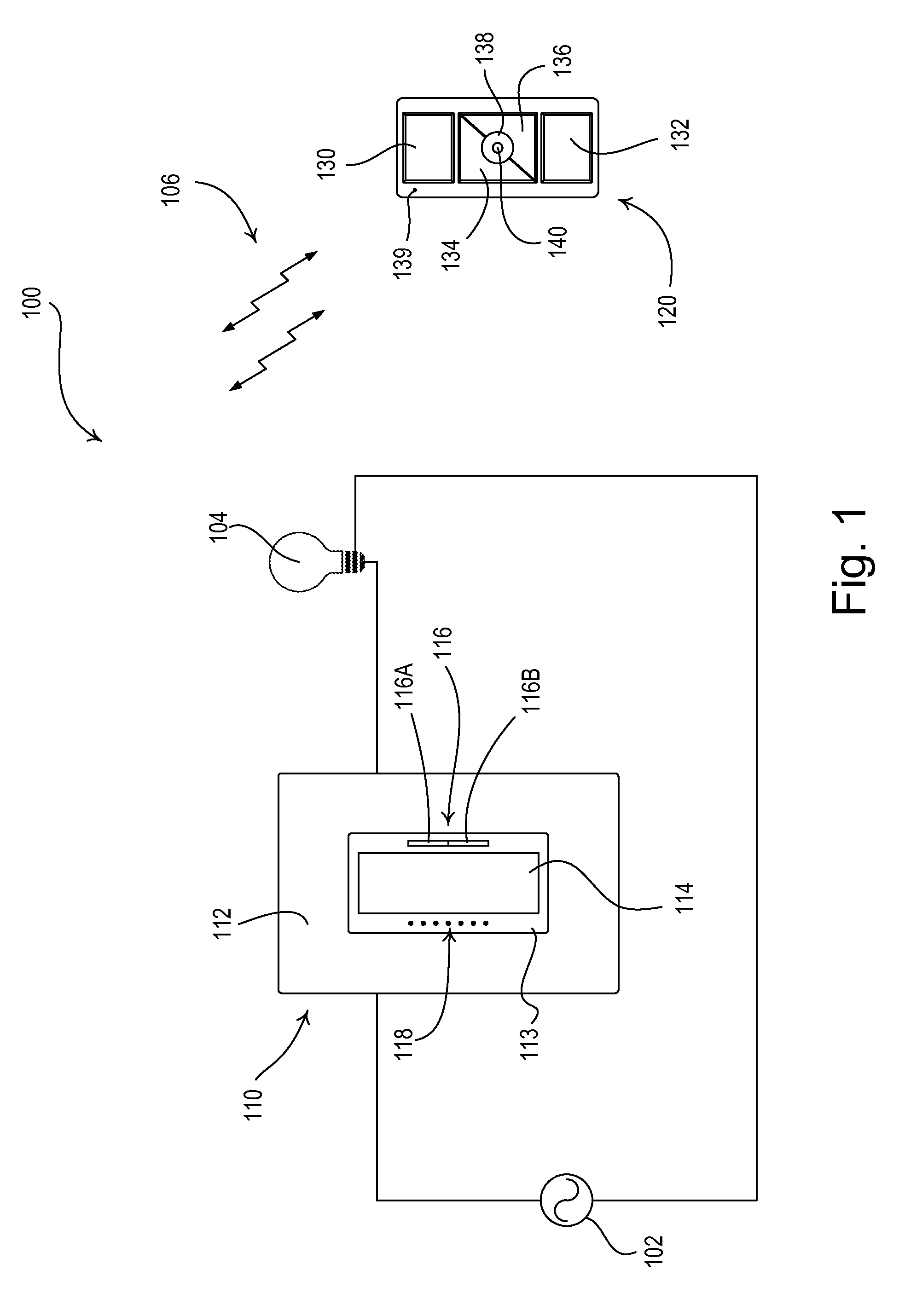
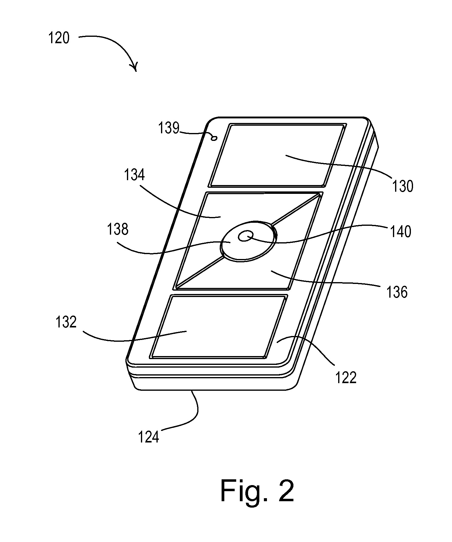
[0051]FIG. 1 is a simple diagram of an RF load control system 100 comprising a remotely-controllable load control device (e.g., a dimmer switch 110) and a battery-powered remote control 120. The dimmer switch 110 is coupled in series electrical connection between an AC power source 102 and an electrical lighting load 104 for controlling the amount of power delivered to the lighting load. The dimmer switch 110 is adapted to be wall-mounted in a standard electrical wallbox, and co...


PUM


Abstract

A control device has a night light that allows the control device to be easily found when the control device is located in a dark space. The control device comprises a low-power night light circuit having an LED characterized by a normal current range. The night light circuit conducts an LED current through the LED in a first mode to illuminate the LED to a first level to provide a night light, where the LED current has a magnitude below the normal current range, such that the night light may be provided in a battery-powered remote control that has an acceptable battery lifetime. The night light circuit is configured to operate in a second mode to illuminate the LED to a second level greater than the first level to provide feedback. The LED current in the second mode has a magnitude within the normal current range of the LED.

Description

CROSS REFERENCES TO RELATED APPLICATIONS[0001]This application is a continuation-in-part of commonly-assigned U.S. patent application Ser. No. 13 / 465,305, filed May 7, 2012, entitled CONTROL DEVICE HAVING A NIGHT LIGHT, which is a non-provisional application of commonly-assigned U.S. Provisional Application No. 61 / 485,885, filed May 13, 2011; U.S. Provisional Application No. 61 / 492,051, filed Jun. 1, 2011; and U.S. Provisional Application No. 61 / 606,644, filed Mar. 5, 2012; all entitled BATTERY-POWERED REMOTE CONTROL HAVING A NIGHT LIGHT. The entire disclosures of all of these applications are hereby incorporated by reference.BACKGROUND OF THE INVENTION[0002]1. Field of the Invention[0003]The present invention relates to a control device, such as a remote control, for a load control system for controlling the amount of power delivered from a source of alternating-current (AC) power to an electrical load, and more particularly, to a battery-powered remote control having a night light...

Claims


Application Information

Patent Timeline
IPC IPC(8): G08C17/02
CPCG08C17/02F21L4/00F21V23/0414F21V33/0052F21Y2115/10G02B6/0008H01H9/0235H01H9/18H01H21/025H01H2217/024H01H2219/039H01H2219/05H01H2219/056H01H2219/062H01H2219/066H01H2221/016H01H2231/032H01H2300/03H05B39/044H05B45/30H05B45/325H05B45/327H05B45/38H05B45/395H05B47/19Y02B20/00Y02B90/20Y04S20/14
Inventor CARMEN, JR., LAWRENCE R.HAKKARAINEN, JUHA MIKKOMANN, TIMOTHYMCDONALD, MATTHEW PHILIP
Owner LUTRON TECH CO LLC
Why Eureka
Eureka Blog
Learn More