
Backlight module

Inactive Publication Date: 2014-05-08
INNOLUX CORP
View PDF6 Cites 8 Cited by
  • Summary
  • Abstract
  • Description
  • Claims
  • Application Information

AI Technical Summary

Benefits of technology

The invention is a backlighting system for displays that uses a mixed-light LED to generate different colors. The color lights can be easily separated to produce a higher color gamut for the display. This technology helps to improve the quality and accuracy of the colors in the display.

Problems solved by technology

However, it is not easy for the green and red lights of the mixed-light (B+RG) LEDs to be separated from each other, thus, limiting the high color gamut of the display.

Method used


Image

  • Backlight module
  • Backlight module
  • Backlight module

Examples


Embodiment Construction

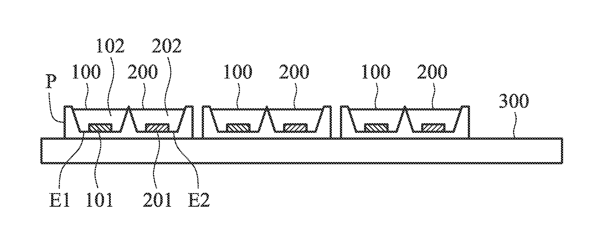
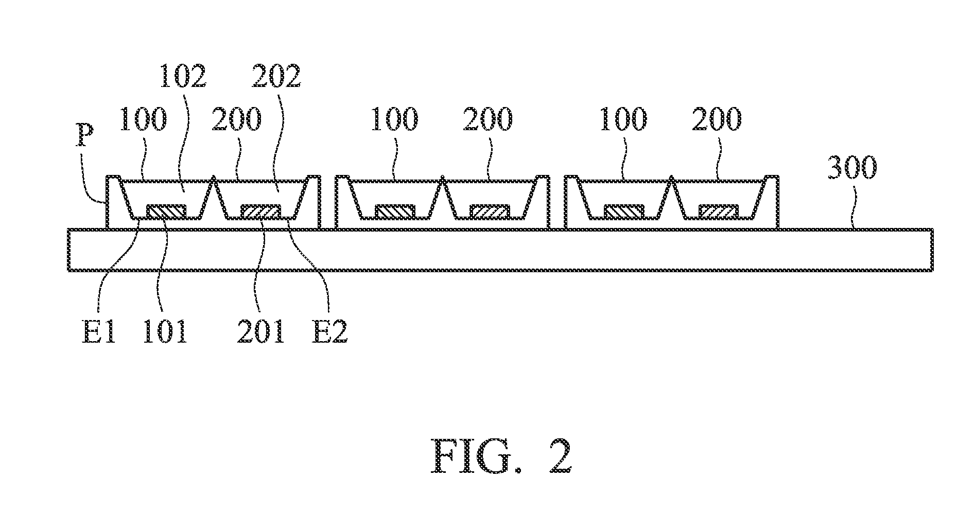
[0019]FIG. 2 is a sectional view of a backlight module according to an embodiment of the invention. As shown in FIG. 2, the backlight module comprises a plurality of first light-emitting devices 100, a plurality of second light-emitting devices 200, a plurality of package units P, and a substrate 300. The package units P are disposed on the substrate 300.

[0020]Each of the package units P includes two recesses E1 and E2 for respectively holding a first light-emitting device 100 and a second light-emitting device 200. Each of the first light-emitting devices 100 comprises a first blue light LED chip 101 and a first phosphor layer 102 covering the first blue light LED chip 101. Similarly, each of the second light-emitting devices 200 comprises a second blue light LED chip 201 and a second phosphor layer 202 covering the second blue light LED chip 201. In this embodiment, the first phosphor layer 102 includes green phosphor particles, and the second phosphor layer 202 includes red phosp...


PUM


Abstract

A backlight module is provided, including a first light-emitting device and a second light-emitting device. The first light-emitting device includes a first blue light LED chip and a first phosphor layer having a first color spectrum, wherein the first color spectrum has a first color spectrum area with at least 70% thereof distributed within the range from 500 nm to 580 nm. The second light-emitting device includes a second blue light LED chip and a second phosphor layer having a second color spectrum, wherein the second color spectrum has a second color spectrum area with at least 60% thereof distributed within the range from 600 nm to 680 nm. The first color spectrum has a portion within the range from 590 nm to 780 nm, and the portion has a first area smaller than or equal to 10% of the second color spectrum area.

Description

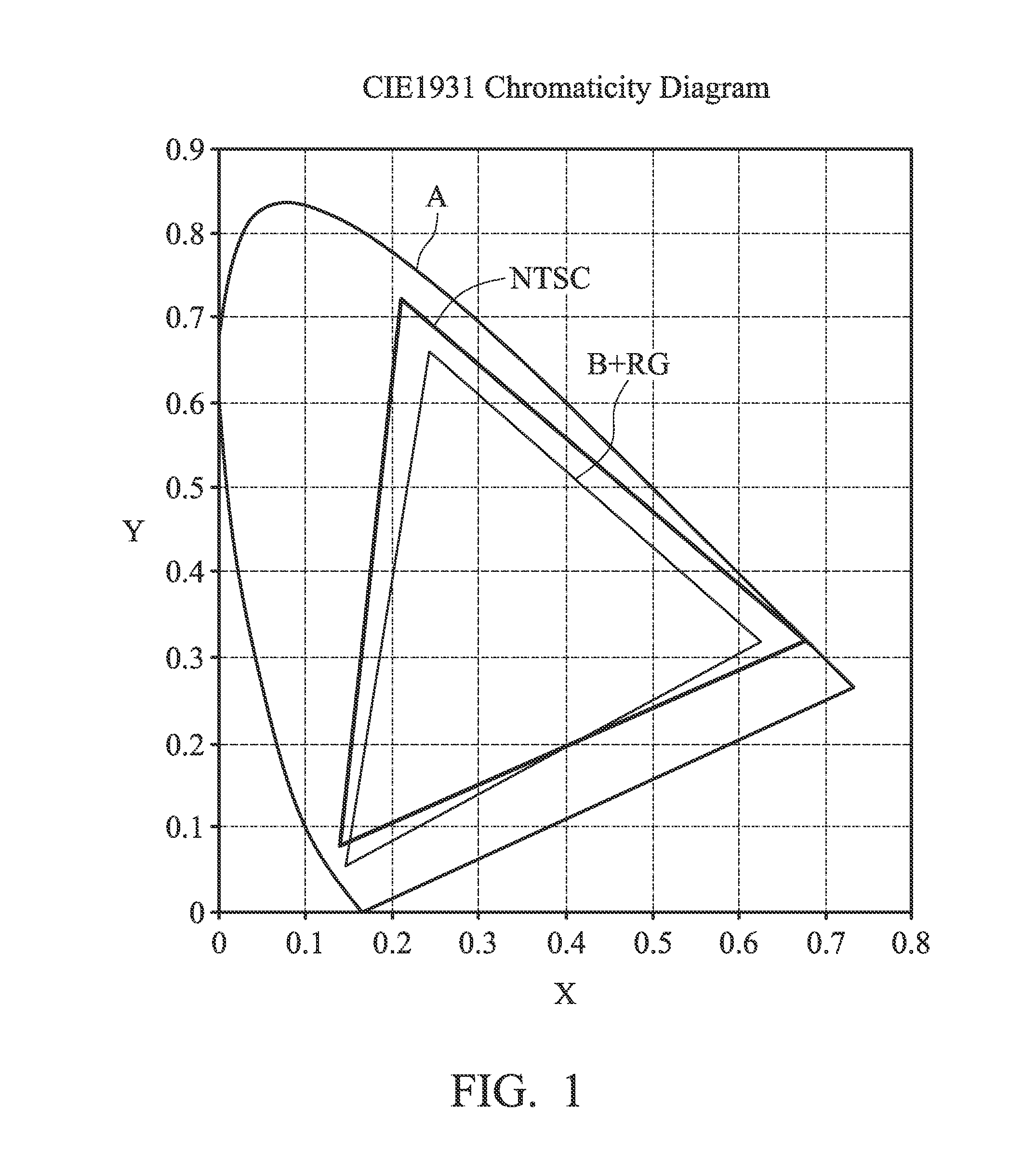
CROSS REFERENCE TO RELATED APPLICATIONS[0001]The present application claims priority of Taiwan Patent Application No. 101140931, filed on Nov. 5, 2012, the entirety of which is incorporated by reference herein.BACKGROUND OF THE INVENTION[0002]1. Field of the Invention[0003]The present application relates to a backlight module, and in particular relates to an LED backlight module.[0004]2. Description of the Related Art[0005]FIG. 1 shows a CIE 1931 chromaticity diagram introduced by the CIE (Commission International De'l E'clairage), wherein the region A in the diagram represents a color gamut defined by the CIE. In FIG. 1, a triangular region B+RG in the region A is defined as a color varying range (i.e. color gamut) of a specific LCD display. Note that, in the field of display, the area ratio of the triangular region B+RG with respect to another triangular region NTSC defined by NTSC (National Television System Committee) can be used as a performance index of the LCD. In general, th...

Claims


Application Information

Patent Timeline
IPC IPC(8): F21K99/00
CPCF21K9/00G02F1/133609G02F1/133614
Inventor HSIEH, MING-FENGHUANG, SHIH-CHANG
Owner INNOLUX CORP
Learn More