Centrifugal fan impeller structure

a centrifugal fan and impeller technology, applied in the direction of non-positive displacement fluid engines, pump components, reaction engines, etc., can solve the problems of non-uniform wake flowing out of the fan impeller, deterioration of the operation performance of electronic components, and burnout of electronic components, so as to reduce noise, increase the blade passing frequency, and reduce the single tone of the blade passing frequency

Active Publication Date: 2014-05-08
ASIA VITAL COMPONENTS SHENZHEN CO LTD
View PDF14 Cites 17 Cited by
  • Summary
  • Abstract
  • Description
  • Claims
  • Application Information

AI Technical Summary

Benefits of technology

[0009]It is therefore a primary object of the present invention to provide an improved centrifugal fan impeller structure, which can reduce noise.
[0010]To achieve the above and other objects, the centrifugal fan impeller structure of the present invention includes a hub having multiple blades. The blades extend from a circumference of the hub in a direction away from the hub. Each two adjacent blades define therebetween a flow way, an air outlet and an air inlet. The air outlet and the air inlet are respectively positioned at two ends of the flow way in communication with the flow way. The air outlets between the blades are selectively arranged at unequal intervals. This can lower the single tone of the blade passing frequency (BPF) and increase the blade passing frequency (BPF) and lower sound pressure weighting so as to greatly reduce noise. In addition, the blade structure can be more flexibly designed according to the boundary condition.

Problems solved by technology

In case the heat is not dissipated in time, the operation performance of the electronic components will be deteriorated.
In some more serious cases, the electronic components may even burn out.
When the centrifugal fan operates, the non-uniform wake flowing out from the fan impeller will interact with the tongue to make noise.
In the case that the gap between the fan impeller and the tongue is relatively narrow, the noise will be affected by the tongue oscillation caused by the impact of the non-uniform wake onto the tongue and the pressure difference around the tongue.
1. The structural design is limited.
2. The conventional centrifugal fan cannot be flexibly designed according to the characteristics.
3. The noise is loud.

Method used


Image

  • Centrifugal fan impeller structure
  • Centrifugal fan impeller structure
  • Centrifugal fan impeller structure

Examples


Embodiment Construction

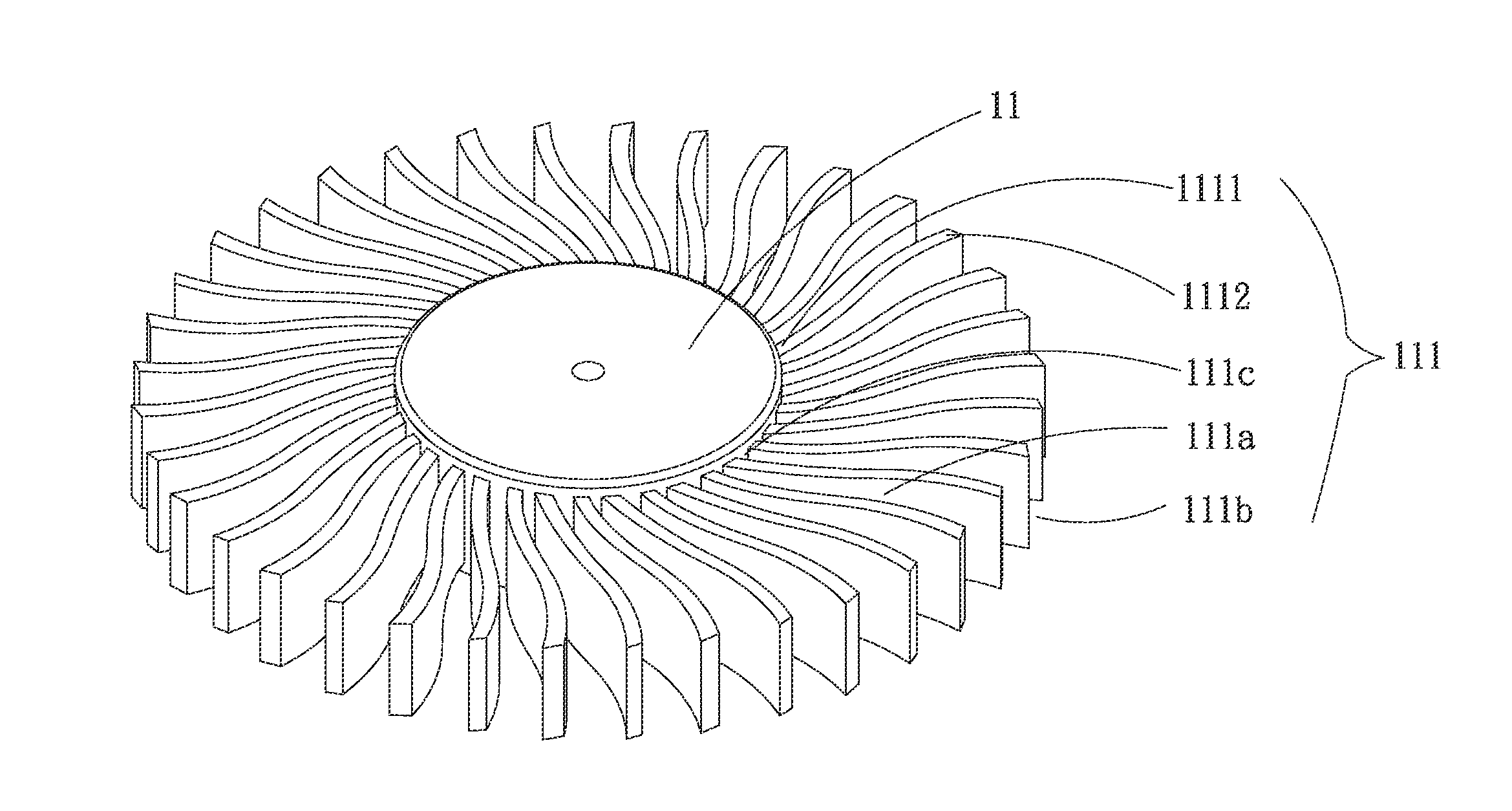
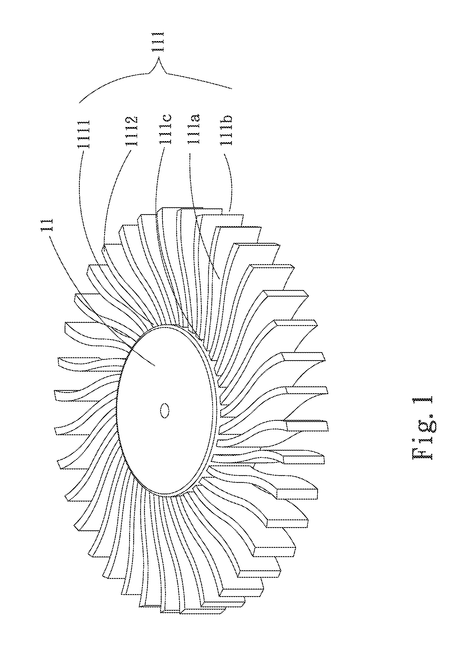
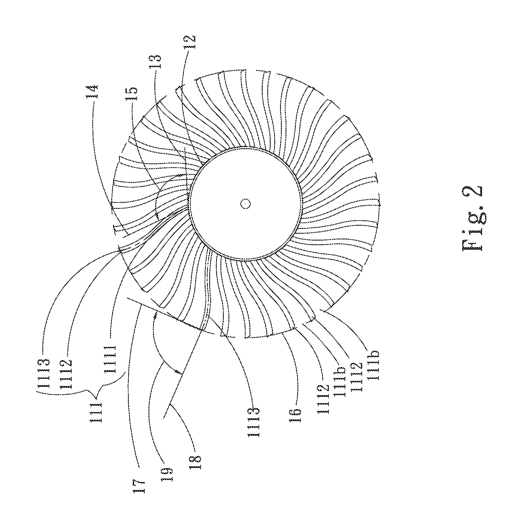
[0016]Please refer to FIGS. 1 and 2. FIG. 1 is a perspective view of a first embodiment of the centrifugal fan impeller structure of the present invention. FIG. 2 is a top view of the first embodiment of the centrifugal fan impeller structure of the present invention. According to the first embodiment, the centrifugal fan impeller structure of the present invention includes a hub 11 having multiple blades 111.

[0017]The blades 111 extend from a circumference of the hub 11 in a direction away from the hub 11. Each two adjacent blades 111 define therebetween a flow way 111a, an air outlet 111b and an air inlet 111c. The air outlet 111b and the air inlet 111c are respectively positioned at two ends of the flow way 111a in communication with the flow way 111a. The air outlets 111b are arranged at unequal intervals.

[0018]Each blade 111 has a first end 1111 and a second end 1112. The air inlet 111c is defined between the first ends 1111 of each two adjacent blades 111. The air outlet 111b ...


PUM


Abstract

A centrifugal fan impeller structure includes a hub having multiple blades. The blades extend from a circumference of the hub in a direction away from the hub. Each two adjacent blades define therebetween a flow way, an air outlet and an air inlet. The air outlet and the air inlet are respectively positioned at two ends of the flow way in communication with the flow way. The air outlets are arranged at unequal intervals so as to greatly reduce noise in operation.

Description

BACKGROUND OF THE INVENTION[0001]1. Field of the Invention[0002]The present invention relates generally to an improved centrifugal fan impeller structure, and more particularly to a centrifugal fan impeller structure, which can reduce noise in operation of the centrifugal fan.[0003]2. Description of the Related Art[0004]Along with the rapid development of electronic industries, the performance of the electronic components has been more and more enhanced. The electronic components have operated at higher and higher speed. In the meantime, the heat generated by the electronic components has become higher and higher. In case the heat is not dissipated in time, the operation performance of the electronic components will be deteriorated. In some more serious cases, the electronic components may even burn out. In order to dissipate the heat, a miniaturized centrifugal fan is installed in a limited space of the system for carrying away the heat. The centrifugal fan includes a frame body, a...

Claims


Application Information

Patent Timeline
Patent Type & Authority Applications(United States)
IPC IPC(8): F04D29/28
CPCF04D29/281F04D29/2216F04D29/666
Inventor YANG, CHIH-WEILEE, SHENG-PEI
Owner ASIA VITAL COMPONENTS SHENZHEN CO LTD
Why Eureka
Try Eureka