Method and system for use in facilitating patch change management of industrial control systems

a technology for industrial control systems and patch changes, applied in the field of cyber asset management of industrial control system software, can solve problems such as the difficulty of tracing and isolating the root cause of a system failure in networked systems, the increase of security vulnerabilities of industrial control systems, and the possibility of far-reaching consequences

Active Publication Date: 2014-05-08
BAKER HUGHES INC
View PDF16 Cites 16 Cited by
  • Summary
  • Abstract
  • Description
  • Claims
  • Application Information

AI Technical Summary

Benefits of technology

[0005]In one embodiment, an offline patch change management system for an industrial facility is provided. The industrial facility includes at least one industrial control system that includes at least one cyber asset. The offline patch change management system includes at least one reader device configured to read patch update information stored on computer-readable storage media inserted therein. The offline patch change management system also includes a memory device coupled to the at least one reader device. The memory device is configured to store the patch update information. The offline patch change management system further includes a processor coupled to the memory device. The processor is programmed to scan the at least one cyber asset. The processor is also programmed to generate a scan report including a patch status for at least one patch not operatively resident on at least one of the at least one cyber asset. The scan report includes a deployment temporal period value for deployment of the at least one patch.
[0006]In another embodiment, an offline method for patch change management of cyber assets is provided. The method includes providing at least one computing device and coupling at least one reader device to the at least one computing device. The method also includes reading patch update information stored on computer-readable storage media using the at least one reader device. The method further includes scanning at least portions of an industrial control system that includes at least one cyber asset. The method also includes generating a scan report including a patch status for at least one patch not operatively resident on the at least one cyber asset. The scan report includes a deployment temporal period value for deployment of the at least one patch.

Problems solved by technology

At least some of such industrial facilities include electric power generation and transmission facilities, transportation systems, dam and water systems, communication systems, chemical and petroleum systems, and other critical facilities that are not intended to tolerate sudden interruptions in service.
However, with the increased size, complexity, and interconnectivity, some industrial control systems have increased security vulnerabilities.
For example, with increased network communications, a single industrial control system component compromise could lead to a much larger cascading failure in adjacent networked systems by allowing unintended, exploitable access.
Tracing and isolating the root cause of a system failure in networked systems becomes much more difficult and with potentially far-reaching consequences.
For example, at least some patch management systems require at least one of manual inventories of previously implemented patches, manual evaluations of currently available patches, and manual trial-and-error patch implementations on test platforms, and such manual efforts are time and resource intensive.
Also, some patches may require the associated industrial control system be taken off line, thereby requiring at least a portion of the system be removed from service for an undetermined period of time with the associated disruption of the facility.
In addition, some patches may require a full system restart once deployed.
Therefore, deployment of some patches may be delayed due to such uncertainties with respect to system and facility impact, thereby rendering unscheduled patching with questionable impact improbable for risk-adverse facilities.
Moreover, some known large industrial customers may require patching activities at many geographically dispersed sites, with a large number of units at each site, making a quick response difficult.
Furthermore, many patch management systems for industrial control systems primarily, or exclusively, address process functionality issues within the original code rather than enhance security.

Method used


Image

  • Method and system for use in facilitating patch change management of industrial control systems
  • Method and system for use in facilitating patch change management of industrial control systems
  • Method and system for use in facilitating patch change management of industrial control systems

Examples


Embodiment Construction

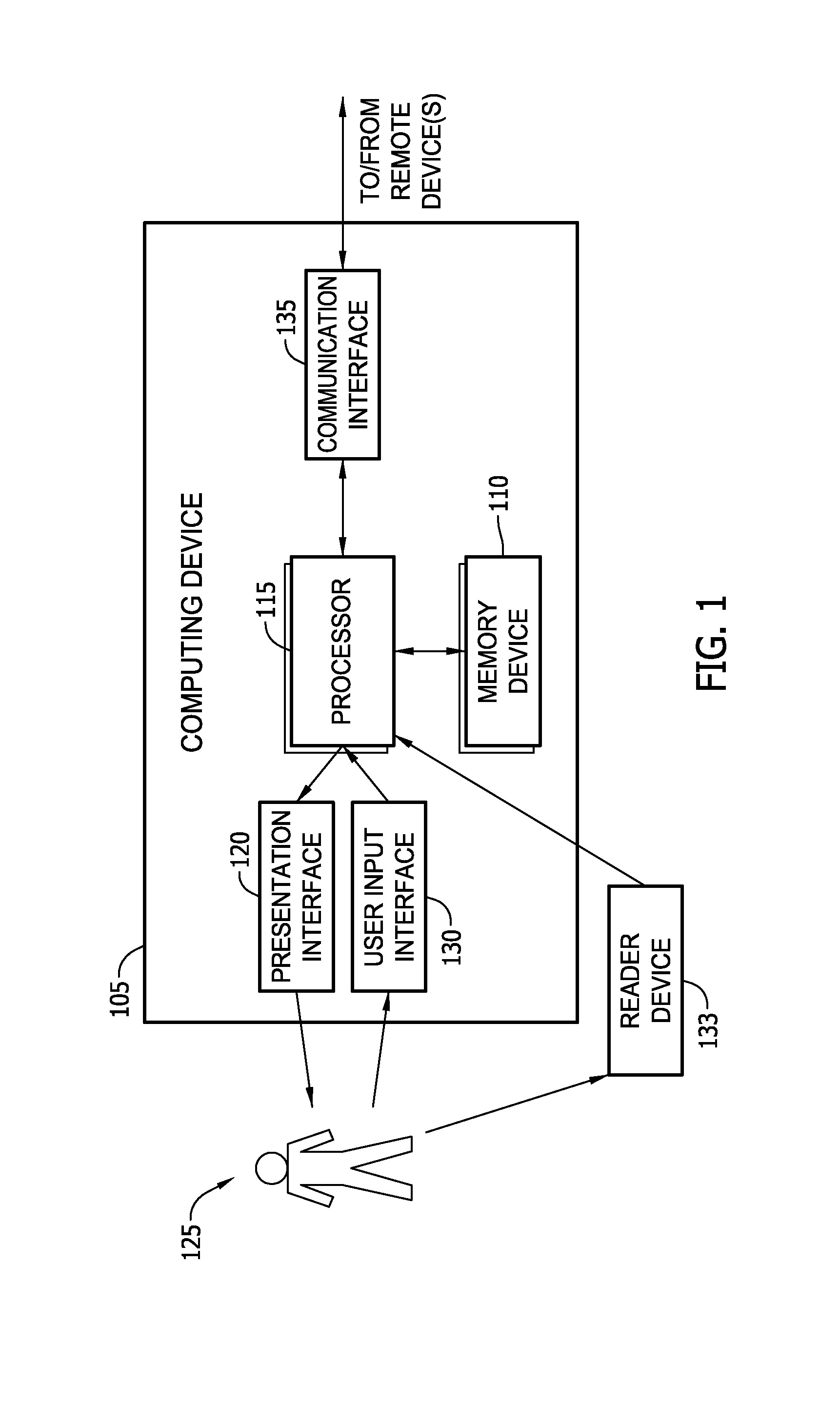
[0013]FIG. 1 is a block diagram of an exemplary computing device 105 that may be used to perform interface activities with any industrial control system (not shown in FIG. 1). Computing device 105 includes a memory device 110 and a processor 115 operatively coupled to memory device 110 for executing instructions. Processor 115 may include one or more processing units (e.g., in a multi-core configuration). In some embodiments, executable instructions are stored in memory device 110. Computing device 105 is configurable to perform one or more operations described herein by programming processor 115. For example, processor 115 may be programmed by encoding an operation as one or more executable instructions and providing the executable instructions in memory device 110. In the exemplary embodiment, memory device 110 is one or more devices that enable storage and retrieval of information such as executable instructions and / or other data. Memory device 110 may include one or more compute...


PUM


Abstract

An offline patch change management system for an industrial facility includes at least one reader device configured to read patch update information stored on computer-readable storage media inserted therein. The industrial facility includes an industrial control system that includes at least cyber asset. The system also includes a memory device coupled to the reader device. The memory device is configured to store the patch update information. The system further includes a processor coupled to the memory device. The processor is programmed to scan the at least one cyber asset. The processor is also programmed to generate a scan report including a patch status for at least one patch not operatively resident on the at least one cyber asset. The scan report includes a deployment temporal period value for deployment of the patch.

Description

BACKGROUND OF THE INVENTION[0001]The present application relates generally to cyber asset management of industrial control system software, and more particularly, to a method and system for use in facilitating patch and update management of industrial control systems.[0002]Many known industrial control systems are installed within industrial facilities that include critical infrastructure. Such known industrial control systems typically include supervisory control and data acquisition (SCADA) systems and process control systems that control, monitor, and manage the execution of the functions associated with the infrastructure based on established parameters and the real-time information they receive. At least some of such industrial facilities include electric power generation and transmission facilities, transportation systems, dam and water systems, communication systems, chemical and petroleum systems, and other critical facilities that are not intended to tolerate sudden interru...

Claims


Application Information

Patent Timeline
Patent Type & Authority Applications(United States)
IPC IPC(8): G06F9/445
CPCG06F8/65
Inventor ALLS, LINDY LAWRENCEPETERSON, SUSAN RUTHTAYLOR, ERIC FIEDLER
Owner BAKER HUGHES INC
Why Eureka
Try Eureka