Non-rotating drill bit for a down-the-hole drill hammer

Active Publication Date: 2014-05-15
CENTER ROCK INC
View PDF9 Cites 5 Cited by
  • Summary
  • Abstract
  • Description
  • Claims
  • Application Information

AI Technical Summary

Benefits of technology

[0007]In accordance with the present invention, the problems associated with the increased complexity of rotational drive mechanisms necessary for conventional DHD hammers are solved by engendering a drill bit for a DHD hammer that does not need to be rotated or

Problems solved by technology

The need to rotate the drill bit in conventional DHD hammers imparts complexity in design of the DHD hammer as it necessitates a mechanism to rotate the drill bit.
Increased complex

Method used


Image

  • Non-rotating drill bit for a down-the-hole drill hammer
  • Non-rotating drill bit for a down-the-hole drill hammer
  • Non-rotating drill bit for a down-the-hole drill hammer

Examples


Embodiment Construction

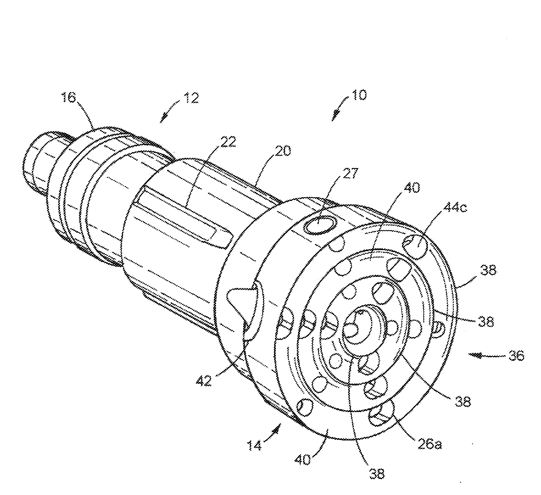
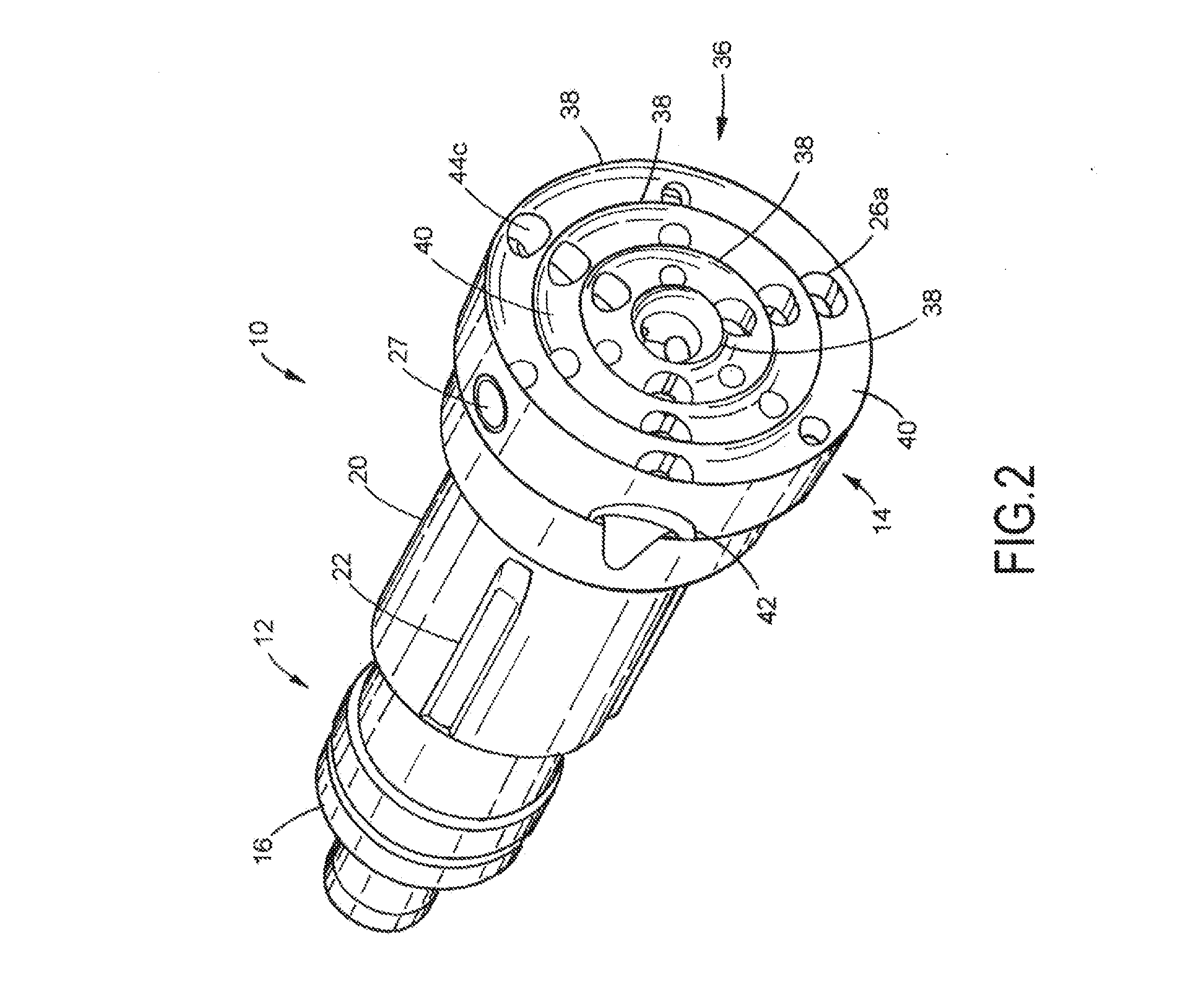
[0040]Reference will now be made in detail to the preferred embodiments of the invention illustrated in the accompanying drawings. Wherever possible, the same or like reference numbers will be used throughout the drawings to refer to the same or like features. It should be noted that the drawings are in simplified form and are not drawn to precise scale. In reference to the disclosure herein, for purposes of convenience and clarity only, directional terms such as top, bottom, above, below and diagonal, are used with respect to the accompanying drawings. Such directional terms used in conjunction with the following description of the drawings should not be construed to limit the scope of the invention in any manner not explicitly set forth. Additionally, the term “a,” as used in the specification, means “at least one.” The terminology includes the words above specifically mentioned, derivatives thereof, and words of similar import.

[0041]Referring to FIGS. 2-12, in a preferred embodim...


PUM


Abstract

A non-rotational drill bit for a down-the-hole drill hammer is provided that includes a head and a shank extending from the head. The head includes a plurality of axisymmetric cutting members about its working face. The drill bit also includes a porting system that includes a central through hole, an air inlet port, an exhaust outlet port and a central exhaust port for exhausting air from an interior of the drill hammer and for clearing drilling debris from the face of the drill bit.

Description

CROSS REFERENCE TO RELATED APPLICATIONS[0001]The present application claims the benefit of priority pursuant to 35 U.S.C. §119(e) of U.S. Provisional Patent Application No. 61 / 724,609, filed Nov. 9, 2012, the entire disclosure of which is hereby incorporated by reference herein.BACKGROUND OF THE INVENTION[0002]The present invention relates generally to down-the-hole drill (DHD) hammers. In particular, the present invention relates to a non-rotating drill bit for a down-the-hole drill hammer.[0003]Typical DHDs include a hammer having a piston that is moved cyclically with high pressure gas (e.g., air). The piston generally has two end surfaces that are exposed to working air volumes (i.e., a return volume and a drive volume) that are filled and exhausted with each cycle of the piston. The return volume pushes the piston away from its impact point on a bit end of the hammer. The drive volume accelerates the piston toward its impact location on the back end of the drill bit. The overal...

Claims


Application Information

Patent Timeline
IPC IPC(8): E21B10/36
CPCE21B10/36E21B10/38E21B10/46
Inventor LYON, LELAND H.
Owner CENTER ROCK INC
Why Eureka
Try Eureka