Liquid ejecting apparatus

a technology of liquid ejector and ejector body, which is applied in the direction of printing, other printing apparatus, etc., can solve the problems of reducing printing quality, printing image, and reducing quality

Inactive Publication Date: 2014-05-15
SEIKO EPSON CORP
View PDF9 Cites 2 Cited by
  • Summary
  • Abstract
  • Description
  • Claims
  • Application Information

AI Technical Summary

Benefits of technology

[0009]An advantage of some aspects of the invention is that a liquid ejecting apparatus which is capable of efficiently preventing undulation of the medium while reducing variation in suction force by using a simple configuration is provided.
[0011]With this configuration, the medium is suctioned through the first suction holes on the first medium support member. Accordingly, variation in the distance between the medium on which the liquid is applied and the liquid ejecting section can be reduced. Further, the suction holes are provided on the second medium support member at positions which correspond to the end portions of the medium in the width direction. Accordingly, the undulation of the medium can be efficiently reduced while preventing variation in suction force by using a simple configuration.
[0013]With this configuration, the step is formed between the first medium support member and the second medium support member. Accordingly, the leading edge of the medium which curves due to curling can be supported by the second medium support member, thereby preventing the medium from being lifted on the first medium support member.
[0015]With this configuration, the recesses are arranged on the first medium support member across the entire length in the width direction with the first suction holes each disposed on the inner bottom surface of the recesses. Accordingly, the medium is suctioned toward inside of the recesses so that the medium is regularly undulated in the width direction, thereby preventing the medium from being irregularly undulated in the transportation direction. Further, the recesses on the first medium support member are disposed at positions which oppose the liquid ejecting section. Accordingly, deviation in landing positions of ink can be reduced by correcting irregular undulation of the medium.
[0016]According to the above aspect of the invention, in the liquid ejecting apparatus, an opening area of each of the second suction holes is larger than an opening area of each of the first suction holes. With this configuration, the second suction holes each have an opening area larger than that of the first suction holes. Accordingly, a larger suction force can be applied on the medium so that the medium is suctioned onto the second medium support member while preventing undulation due to swelling.

Problems solved by technology

This causes deviation in landing position of ink on the sheet of paper (roll paper), leading to reduced printing quality.
If the surface of the sheet of paper which is undulated due to swelling comes into contact with a liquid ejecting section or parts near the liquid ejecting section, the printed image has a defect, thereby reducing the quality.
However, as the number of suction holes increases, the problem arises that the suction force applied on the sheet of paper largely varies depending on the number of suction holes which are covered with the sheet of paper during transportation of the sheet of paper.
Further, if a plurality of suction mechanisms that apply suction force on the sheet of paper is provided corresponding to a plurality of groups of suction holes and is selectively actuated to prevent the suction force from varying, the problem arises that a configuration of the apparatus becomes complicated.
The above problems are present not only in printers that print on a roll paper but also in liquid ejecting apparatuses in general that eject liquid onto a medium which is suctioned onto a medium support member.

Method used


Image

  • Liquid ejecting apparatus
  • Liquid ejecting apparatus
  • Liquid ejecting apparatus

Examples


Embodiment Construction

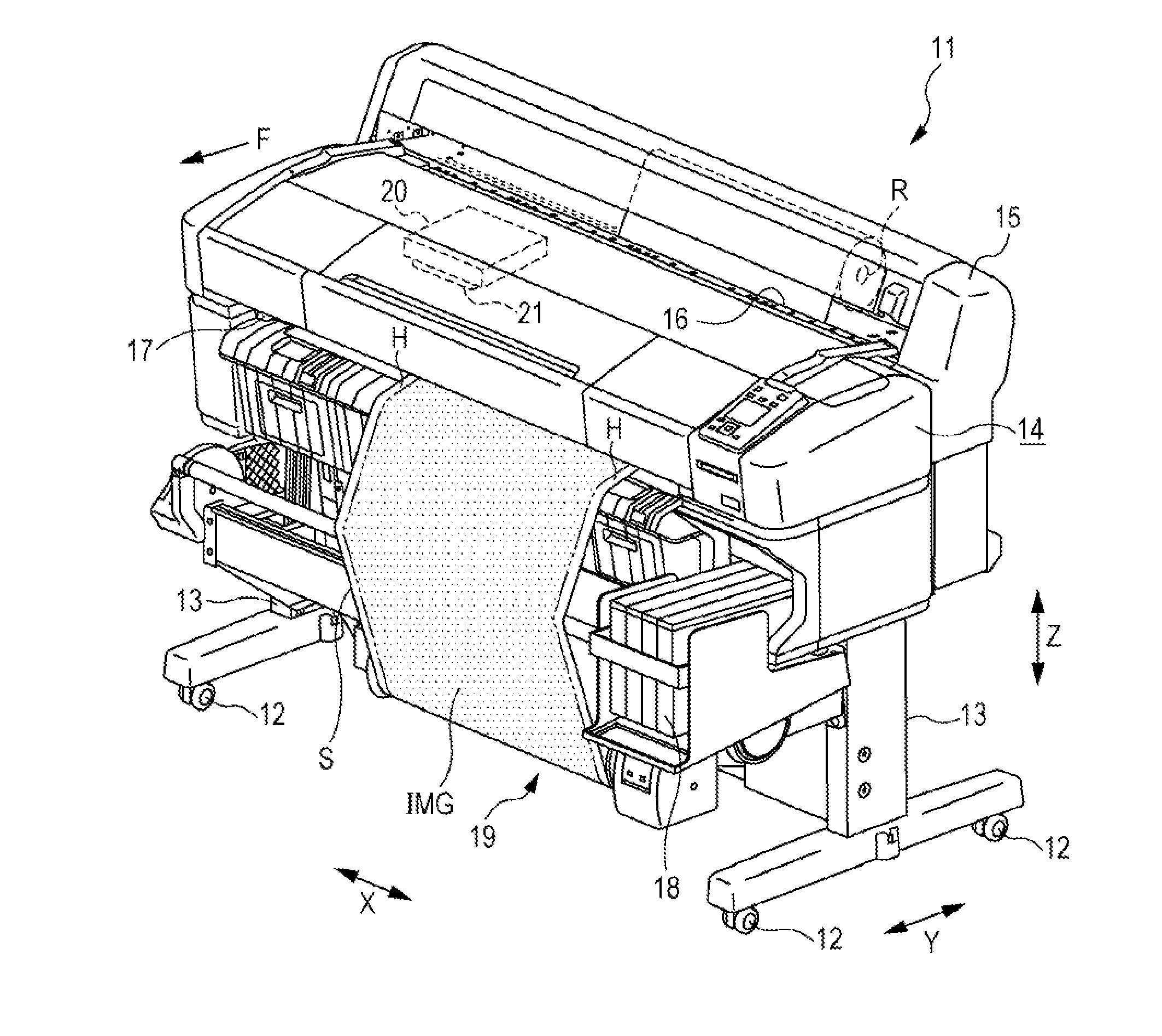
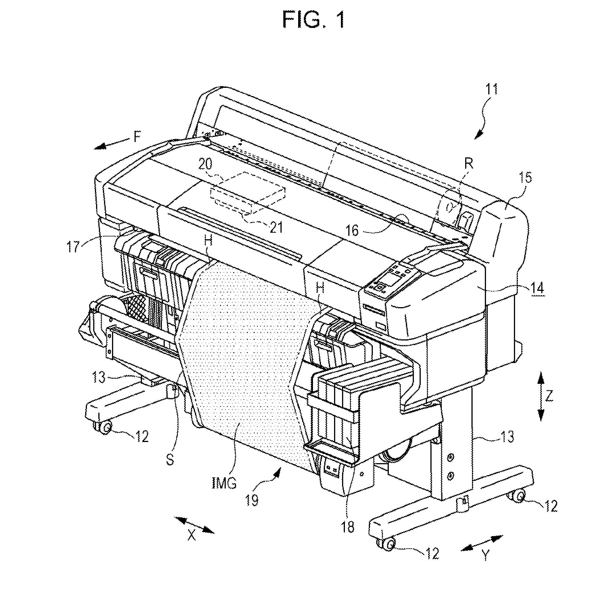
[0027]An embodiment of a liquid ejecting apparatus will be described below with reference to the drawings. As shown in FIG. 1, a liquid ejecting apparatus 11 of this embodiment includes legs 13 with wheels 12 mounted on the lower end of the respective legs 13 and a housing 14 which is assembled on the legs 13. In this embodiment, a longitudinal direction of the housing 14 is defined as a width direction X, which traverses (in this embodiment, which is perpendicular to) an up-down direction Z that extends in the gravitational direction. Further, a direction which traverses (in this embodiment, which is perpendicular to) both the up-down direction Z and the width direction X is defined as a front-back direction Y.

[0028]A feeding unit 15 is provided on the back side of the housing 14 and extends upward. A roll R formed of a paper sheet S which is an example of a medium rolled into a cylindrical shape is loaded in the feeding unit 15. In this embodiment, the paper sheet S is a roll pape...


PUM


Abstract

A liquid ejecting apparatus includes a liquid ejecting section that ejects ink onto a paper-sheet which is transported in a transportation-direction; a first medium support member that supports the paper-sheet and has suction holes which allow a suction force to be applied on the paper-sheet, the suction holes being arranged on the first medium support member in a width-direction which is perpendicular to the transportation-direction; and a second medium support member that supports the paper-sheet and has suction holes which allow a suction force to be applied on the paper-sheet, the suction holes being arranged in pairs on the second medium support member at positions which correspond to end portions of the paper-sheet in the width-direction, wherein the distance between a pair of suction holes on the second medium support member in the width-direction is larger than that between the adjacent suction holes on the first medium support member.

Description

BACKGROUND[0001]1. Technical Field[0002]The present invention relates to liquid ejecting apparatuses that eject liquid onto a medium which is suctioned onto a medium support member.[0003]2. Related Art[0004]Liquid ejecting apparatuses that are capable of ejecting liquid include ink jet printers that perform printing on a roll paper by ejecting ink onto a sheet of paper of the roll when the sheet of paper is transported on a medium support member. Since the sheet of paper is held in a cylindrically rolled state, the sheet of paper has curling in the longitudinal direction and may be lifted from the surface of the medium support member. This causes deviation in landing position of ink on the sheet of paper (roll paper), leading to reduced printing quality.[0005]JP-A-2007-276960 discloses a printer that performs printing on a roll paper and the like. The printer prevents a sheet of paper from being lifted due to curling by applying a suction force on the sheet of paper through suction ...

Claims


Application Information

Patent Timeline
Patent Type & Authority Applications(United States)
IPC IPC(8): B41J11/00
CPCB41J11/0005B41J11/0085B41J11/06
Inventor SHIMADA, YOSHITAKAOGURA, KIYOTAKA
Owner SEIKO EPSON CORP
Why Eureka
Try Eureka