
Indication And Processing Method And Device For Resource Occupancy Mode

Active Publication Date: 2014-05-15
DATANG MOBILE COMM EQUIP CO LTD
View PDF3 Cites 26 Cited by
  • Summary
  • Abstract
  • Description
  • Claims
  • Application Information

AI Technical Summary

Benefits of technology

This patent provides a method and device for a resource occupancy scheme that helps a user equipment (UE) understand which parts of a wireless network are using which resources to transmit control information. By doing so, the UE can avoid unnecessary power consumption and interference with other signals. The base station determines which parts of the network are using which resources to transmit control information and sends a message to the UE explaining which resources are being used. The UE then uses these resources to detect and handle the control information. The technical effect of this patent is to improve the efficiency and performance of wireless networks by reducing power consumption and interference.

Problems solved by technology

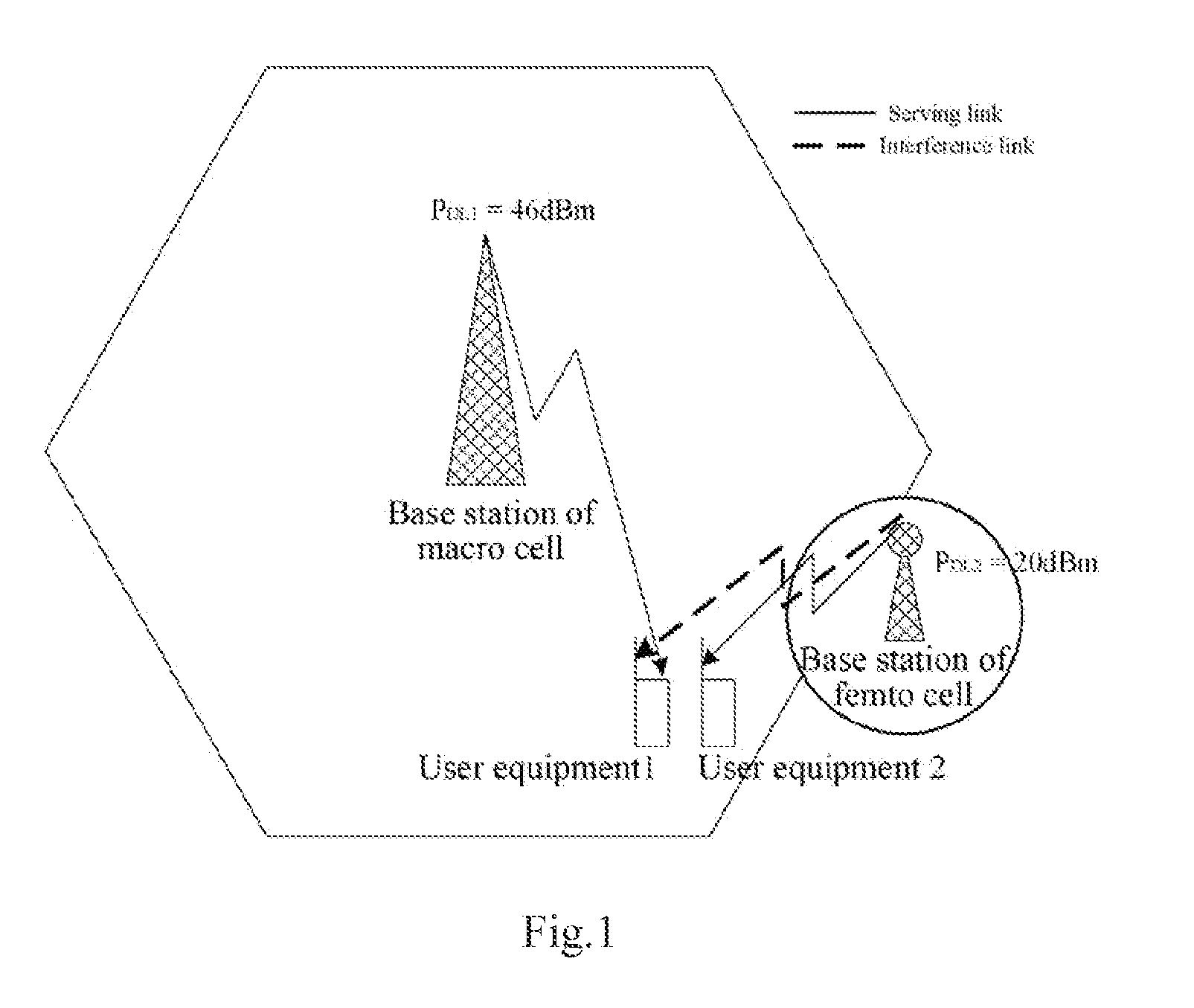
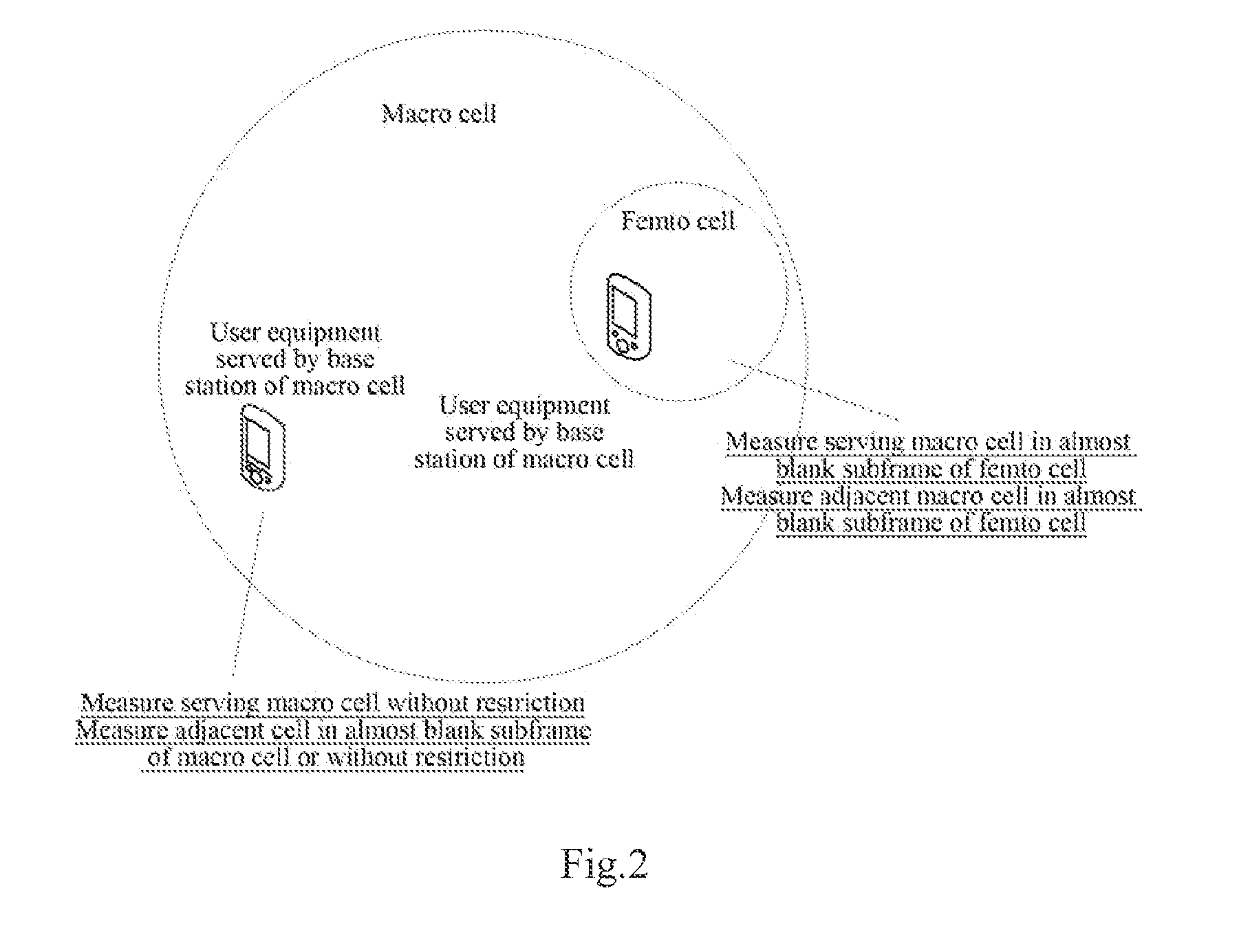
Along with a constantly increasing data rate and service load as required, a conventional access over single-layer coverage by a macro base station has failed to satisfy the demand, and consequently existing systems have come to gradually attempt an access over layered coverage, that is, some low-power base stations, e.g., a Home eNodeB, a pico base station, a femto base station, a relay node, etc., are deployed in a hotspot area or indoors to cooperate with the macro base station for signal coverage to thereby well satisfy the constantly increasing demand.
If the pico base station is at the same frequency as the macro base station, then the subscriber also may become inoperative due to strong interference, and also the interference problem has to be addressed with use of an ABS subframe based upon the TDM ICIC mechanism.

Method used


Image

  • Indication And Processing Method And Device For Resource Occupancy Mode
  • Indication And Processing Method And Device For Resource Occupancy Mode
  • Indication And Processing Method And Device For Resource Occupancy Mode

Examples


Embodiment Construction

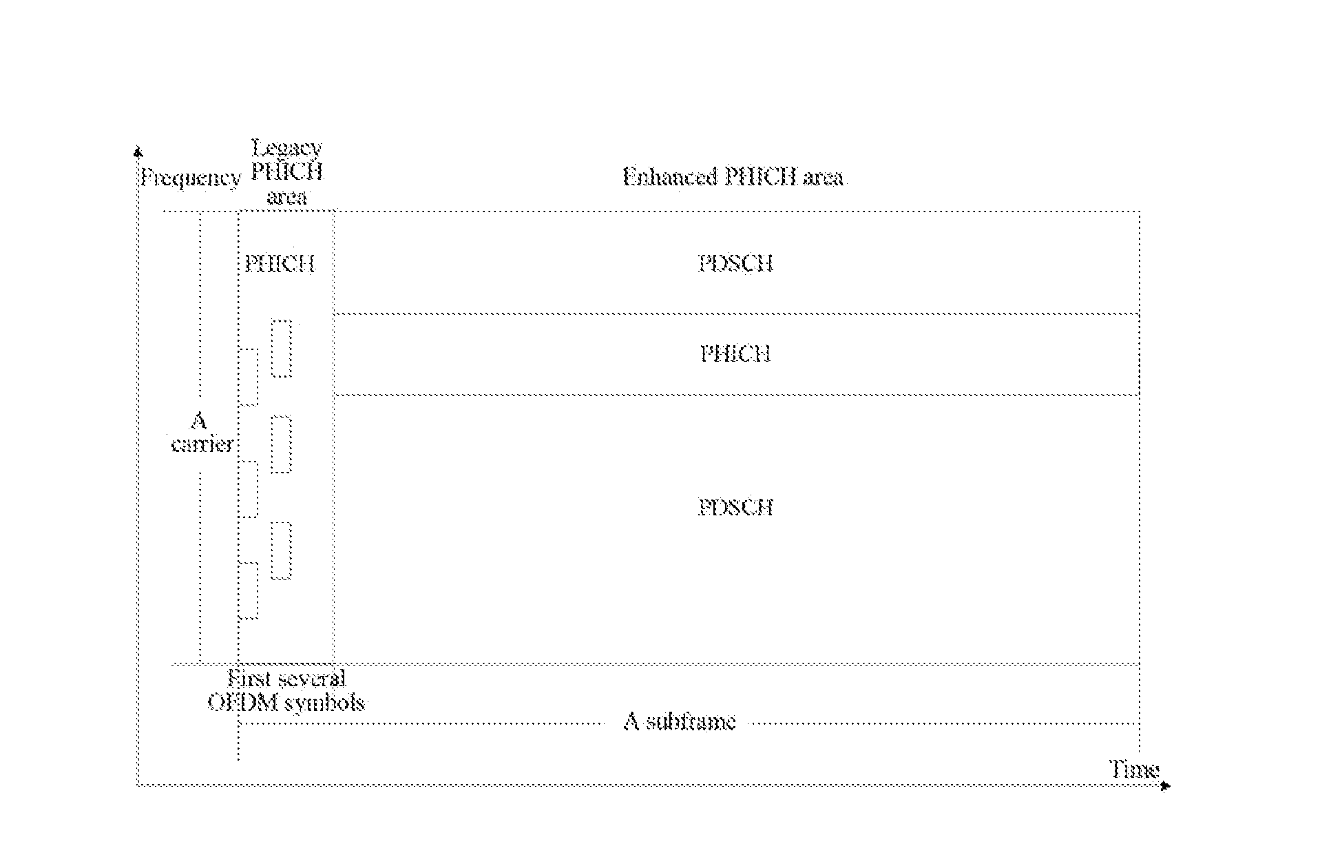
[0039]In a communication system with use of a TDM ICIC mechanism, legacy PDCCH resources available to an interfering base station and a victim base station have been lowered for interference obviation, and in order to avoid the problem of a limited capacity of the system, a search space is extended by extended PDCCHs at the network side to thereby ensure the capacity of the system in embodiments of the invention.

[0040]On the other hand, in the communication system with use of the TDM ICIC mechanism, uplink transmission of the interfering base station and the victim base station may have been limited for interference obviation, and in order to ensure uplink service transmission of the system, uplink subframes are scheduled in an enhanced scheduling scheme (for example, a multi-frame or cross-subframe scheduling scheme) in embodiments of the invention. For example, referring to FIG. 5, no uplink subframe can be scheduled in the downlink subframes 2 and 6 configured as ABS subframes, s...


PUM


Abstract

There is disclosed a method of indicating a resource occupancy scheme and processing a resource occupancy scheme indicator so as to enable a UE to be aware a resource occupancy scheme of the network side and avoid an unnecessary power waste and unnecessary interference, and in the method, a base station generates a corresponding resource indicator for a resource occupancy scheme of a legacy control resource area and an enhanced control resource area in each downlink subframe to be transmitted in a specific periodicity and sends the resource indicator to a UE in a resource indication message, and the UE determines from the obtained resource indicator the resource occupancy scheme of the legacy control resource area and the enhanced control resource area in each downlink subframe to be transmitted in the specific periodicity and performs a corresponding resource handling mode, so that the UE can blindly detect in PDCCH common and user spaces or receive control information carried on PHICH resource at an accurate position to thereby avoid an unnecessary power waste of and unnecessary interference to the UE due to blind detection or reception and improve effectively the performance of a system.

Description

[0001]This application claims the benefit of Chinese Patent Application No. 201110144852.4, filed with the Chinese Patent Office on May 31, 2011 and entitled “Method of and apparatus for indicating resource occupancy scheme and processing resource occupancy scheme indicator”, which is hereby incorporated by reference in its entirety.FIELD OF THE INVENTION[0002]The present invention relates to the field of communications and particularly to a method of and apparatus for indicating a resource occupancy scheme and processing a resource occupancy scheme indicator.BACKGROUND OF THE INVENTION[0003]Along with a constantly increasing data rate and service load as required, a conventional access over single-layer coverage by a macro base station has failed to satisfy the demand, and consequently existing systems have come to gradually attempt an access over layered coverage, that is, some low-power base stations, e.g., a Home eNodeB, a pico base station, a femto base station, a relay node, e...

Claims


Application Information

Patent Timeline
IPC IPC(8): H04J3/16
CPCH04J3/1694H04L5/0053H04W84/045H04L5/0094H04L1/1861H04L5/0092H04L5/14H04L5/1469H04W72/23H04B7/2603H04B7/2612
Inventor PENG, YINGPAN, XUEMINGZHAO, RUI
Owner DATANG MOBILE COMM EQUIP CO LTD
Learn More