Highly integrated leading edge of an aircraft lifting surface

a leading edge and aircraft technology, applied in the direction of marine propulsion, vessel parts, vessel construction, etc., can solve the problems of high cost of a leading edge manufactured with said method, high overall manufacturing cost, and difficulty in the demoulding process

Active Publication Date: 2014-05-15
AIRBUS OPERATIONS SL
View PDF4 Cites 13 Cited by
  • Summary
  • Abstract
  • Description
  • Claims
  • Application Information

AI Technical Summary

Benefits of technology

[0010]It is an object of the present invention to provide a method for manufacturing a monolithic leading edge profile section for reducing the number of different elements of the leading edge of an aircraft lifting surface to be manufactured and installed.

Problems solved by technology

The cost of a leading edge manufactured with said method is high because said steps shall be carried out independently for each element and a final assembly stage is needed.
Nevertheless, the tooling set required to build the whole element is complex making the demoulding process difficult and the overall manufacturing costs still high.

Method used


Image

  • Highly integrated leading edge of an aircraft lifting surface
  • Highly integrated leading edge of an aircraft lifting surface
  • Highly integrated leading edge of an aircraft lifting surface

Examples


Embodiment Construction

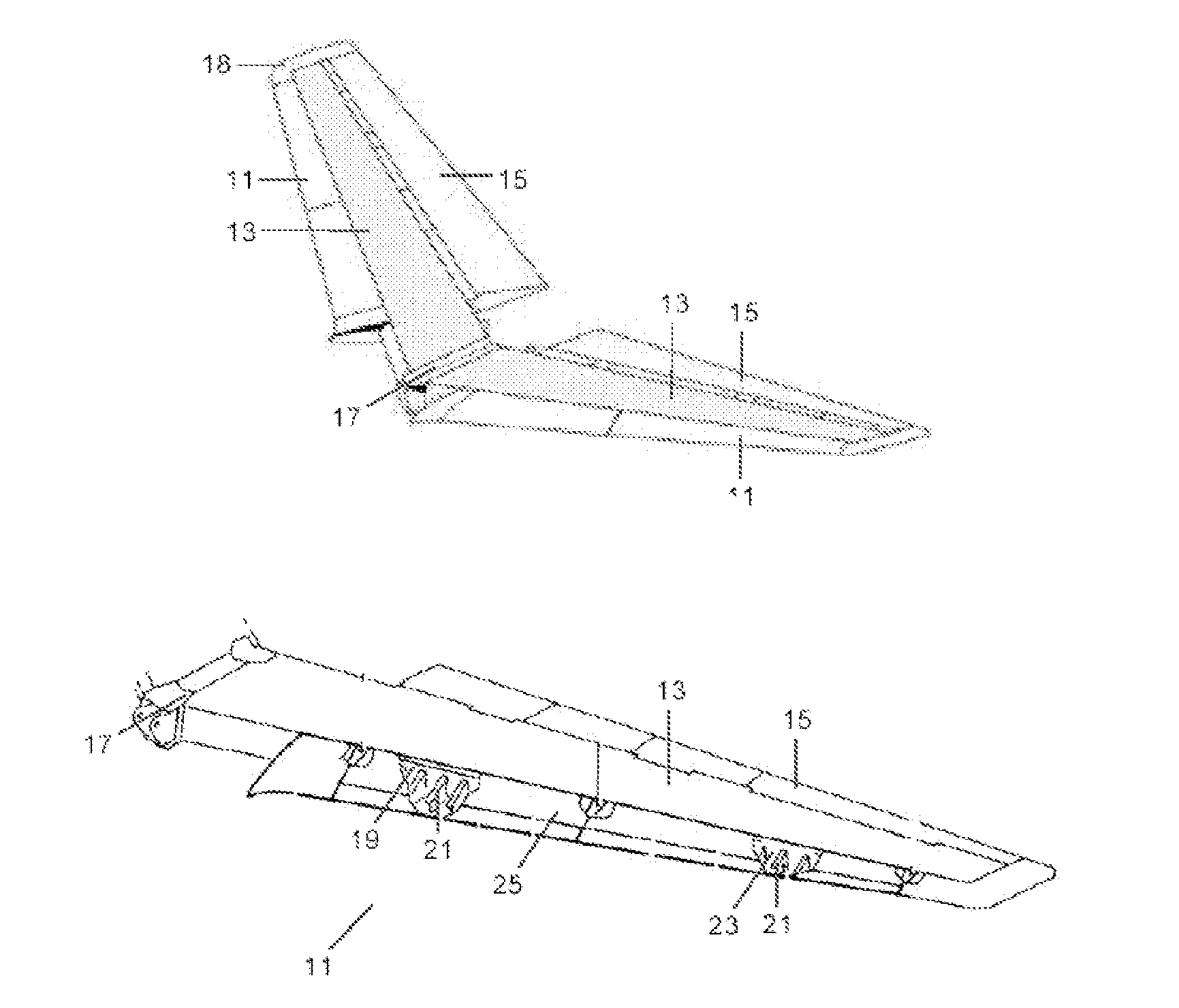
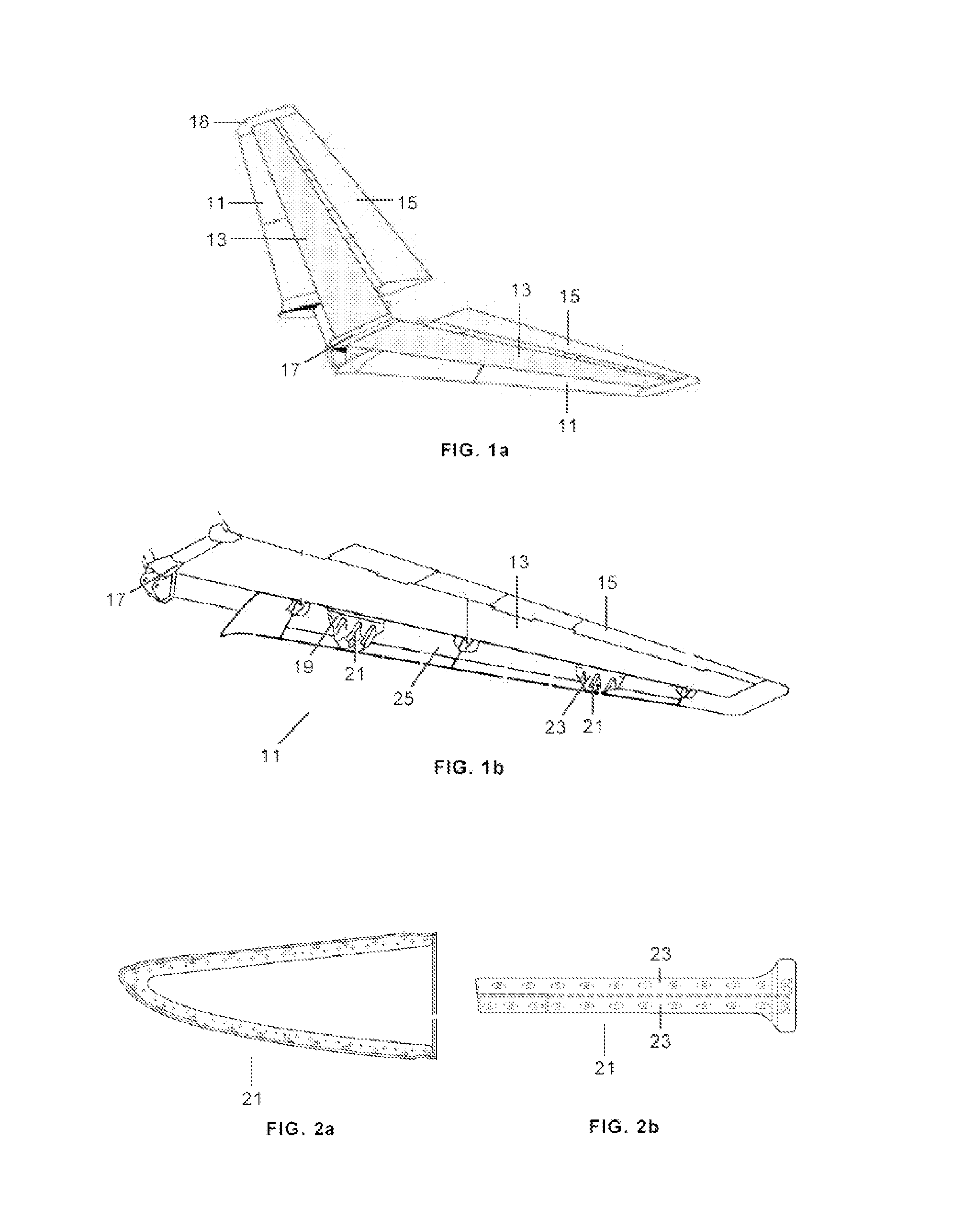
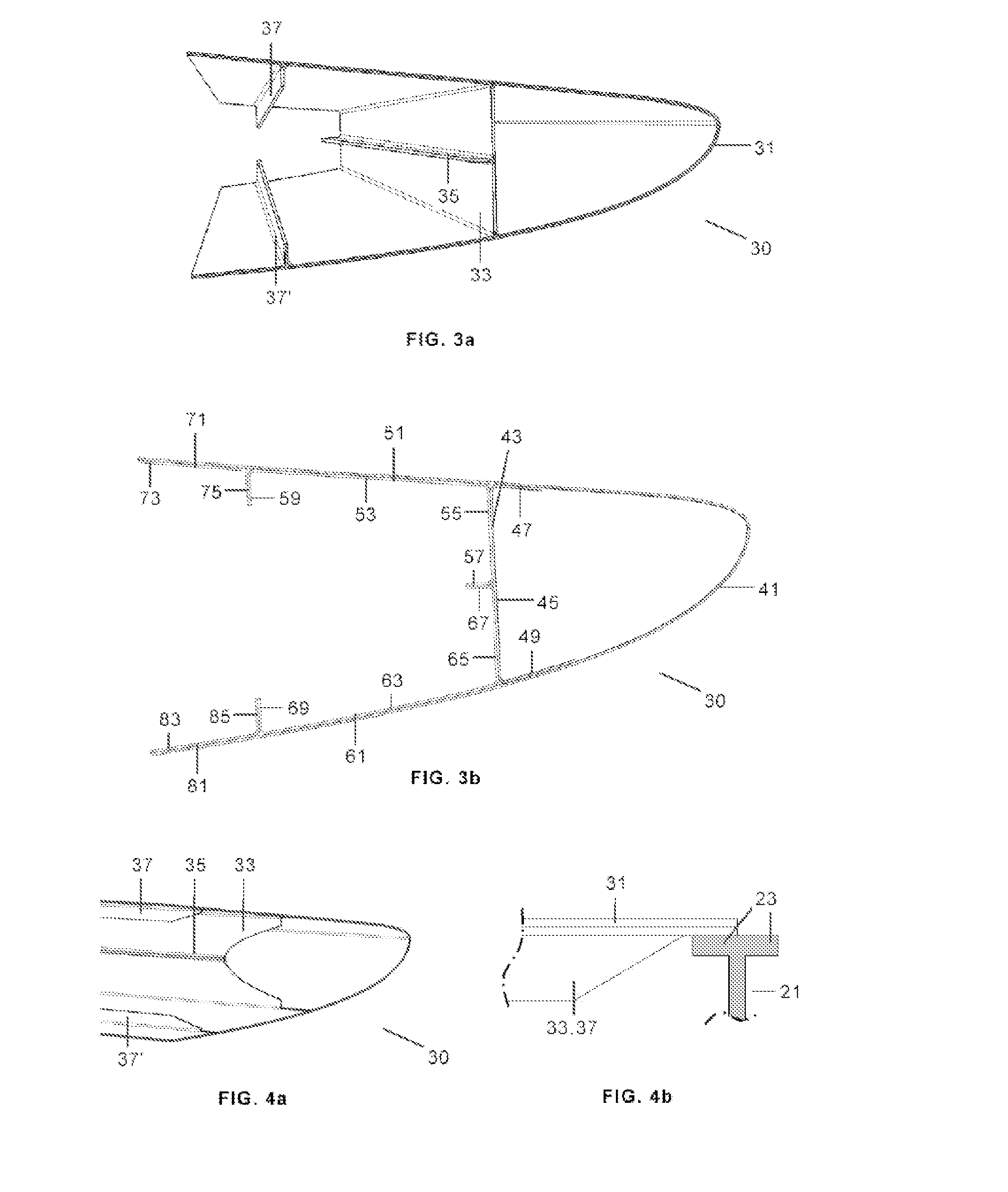
[0034]FIG. 3a shows a monolithic leading edge profile section 30 according to the invention comprising a leading edge skin 31 and a longitudinal auxiliary spar 33. All the leading edge profile sections 30 are attached to the leading edge ribs 21 and to the frontal spar in a similar manner to the above-mentioned known leading edges.

[0035]The position of the auxiliary spar 33 could be closer or farther from the front spar 19 of the torsion box 13 depending on the aerodynamic profile geometry, manufacturing constraints, bird impact analysis results and any other certification requirements.

[0036]The leading edge profile 30 also comprises one longitudinal stiffener 35 of the auxiliary spar 33 arranged perpendicularly to it in the middle of its height in order to reinforce the web of the auxiliary spar 33 to improve its structural behavior to support the loads involved and bird impacts. The thickness and height of this longitudinal stiffener 35 are a function of the specific structural an...


PUM

PropertyMeasurementUnit
heightaaaaaaaaaa
planar shapeaaaaaaaaaa
curved shapeaaaaaaaaaa

Abstract

A method for manufacturing a leading edge profile section of an aircraft lifting surface is provided. The method comprises the following steps: a) providing a set of laminated preforms of a composite material configured with a suitable shape for constituting the leading edge profile section; b) arranging said laminated preforms in a curing tooling and subjecting the assembly to an autoclave cycle to co-cure said laminated preforms; c) demoulding the curing tooling in a spanwise direction towards the aircraft symmetry plane. The invention also comprises a leading edge profile section manufactured by said method comprising in addition to the skin of the leading edge profile section, one or more of the following structural elements: an auxiliary spar, a longitudinal stiffener reinforcing an auxiliary spar, a longitudinal stringer reinforcing the skin of the leading edge profile.

Description

FIELD OF THE INVENTION [0001]The present invention refers to the leading edge of an aircraft lifting surface and more in particular to highly integrated leading edge of an aircraft lifting surface.BACKGROUND OF THE INVENTION [0002]An aircraft lifting surface (see FIG. 1a) is usually structured by leading edges 11, torsion boxes 13, trailing edges 15 with control surfaces (flaps, elevators, rudders, etc.), a root joint 17 and tips 18.[0003]A leading edge 11 is a structure responsible for keeping the aerodynamic surface with a torsion box surface, for supporting the static or cyclic structural loads involved and for protecting the torsion box from bird impacts. It is the part of the lifting surface that first contacts the air and the foremost edge of an airfoil section.[0004]A known leading edge 11 (see FIG. 1b) comprises, on the one side, several ribs 21, called leading edge ribs (see FIGS. 2a, 2b), attached to the front spar 19 of the torsion box 13 and, on the other side, an aerody...

Claims


Application Information

Patent Timeline
Patent Type & Authority Applications(United States)
IPC IPC(8): F01D5/14
CPCF01D5/14B64C3/28B29D99/0028Y10T29/49336
Inventor GUINALDO FERNANDEZ, ENRIQUEHONORATO RUIZ, FRANCISCO JAVIERCRUZ DOMINGUEZ, FRANCISCO JOSE
Owner AIRBUS OPERATIONS SL
Why Eureka
Try Eureka