Catheter with flat beam deflection in tip

a catheter and tip technology, applied in the field of medical devices, can solve the problems of reducing and imposing significant stress on the puller wire, so as to reduce the size of the catheter, reduce the force required to bend the deflection beam, and increase the durability of the puller wire

Active Publication Date: 2014-05-15
BIOSENSE WEBSTER (ISRAEL) LTD
View PDF5 Cites 16 Cited by
  • Summary
  • Abstract
  • Description
  • Claims
  • Application Information

AI Technical Summary

Benefits of technology

[0010]The present invention is directed to a catheter having a deflection beam and a single continuous puller wire to effectuate predictable on-plane bi-directional deflection with less deflection components for reducing catheter size without compromising functionality, including the ability to carry, house and support mapping and / or ablation components, such as a multitude of electrodes and lead wires. The catheter includes an elongated catheter body, a deflectable section, a distal assembly carrying diagnostic and / or therapeutic electrodes, and a control handle. For bi-directional deflection, the deflection beam of the deflectable section has a rectangular cross section with first and second opposing surfaces defining corresponding first and second opposing directions of deflection. Acting on the deflection beam, the single continuous puller wire has a U-bend at or near a midpoint of the wire, which is anchored at a distal end of the deflection beam. Extending proximally therefrom are first and second proximal segments of the puller wire which extend in parallel with the deflection beam through the deflectable section on opposite sides of the beam along the first and second surfaces, respectively. The first and second proximal segments further extend proximally through the catheter body and into the control handle where proximal ends of the puller wire are anchored. To minimize the force required to bend the deflection beam, each proximal segment extending along the deflection beam is guided, maintained and / or bounded to the beam at a predetermined separation distance from the beam surface by a spacer. The spacers also increase durability of the puller wires by providing a geometry that allows tensile load with minimal shear stress.

Problems solved by technology

In this arrangement, lengthwise movement of the piston relative to the housing results in deflection of the catheter tip section.
However, the puller wire in tension under deflection often flips over to the other side of the beam, or where the puller wires are located close to the beam, a large bending moment is required to deflect the beam, imposing significant stress on the puller wires.
Moreover, with the puller wires close and tightly constrained to the beam, adhesion failure or rupture of the puller wire from the beam poses a significant risk of injury to the patient.
More components also increased the risk of component failures.
The use of T-bars and / or crimps can unduly fatigue puller wires and impart shear stresses resulting from skewed or off-axis alignment of puller wires relative to the longitudinal axis of the catheter, even if by a minor degree.
A catheter of a uniform width along its length may not be well adapted for use in such tubular regions.
For example, a deflectable tip with a larger french size may impede cannulation and tracking in a smaller tubular region and a deflectable tip with a smaller French size may not be stable in a larger tubular region.
Abutting ends of tubings covering the beam at the joint may separate and detach from each other due to excessive torsional or axial forces.

Method used


Image

  • Catheter with flat beam deflection in tip
  • Catheter with flat beam deflection in tip
  • Catheter with flat beam deflection in tip

Examples


Embodiment Construction

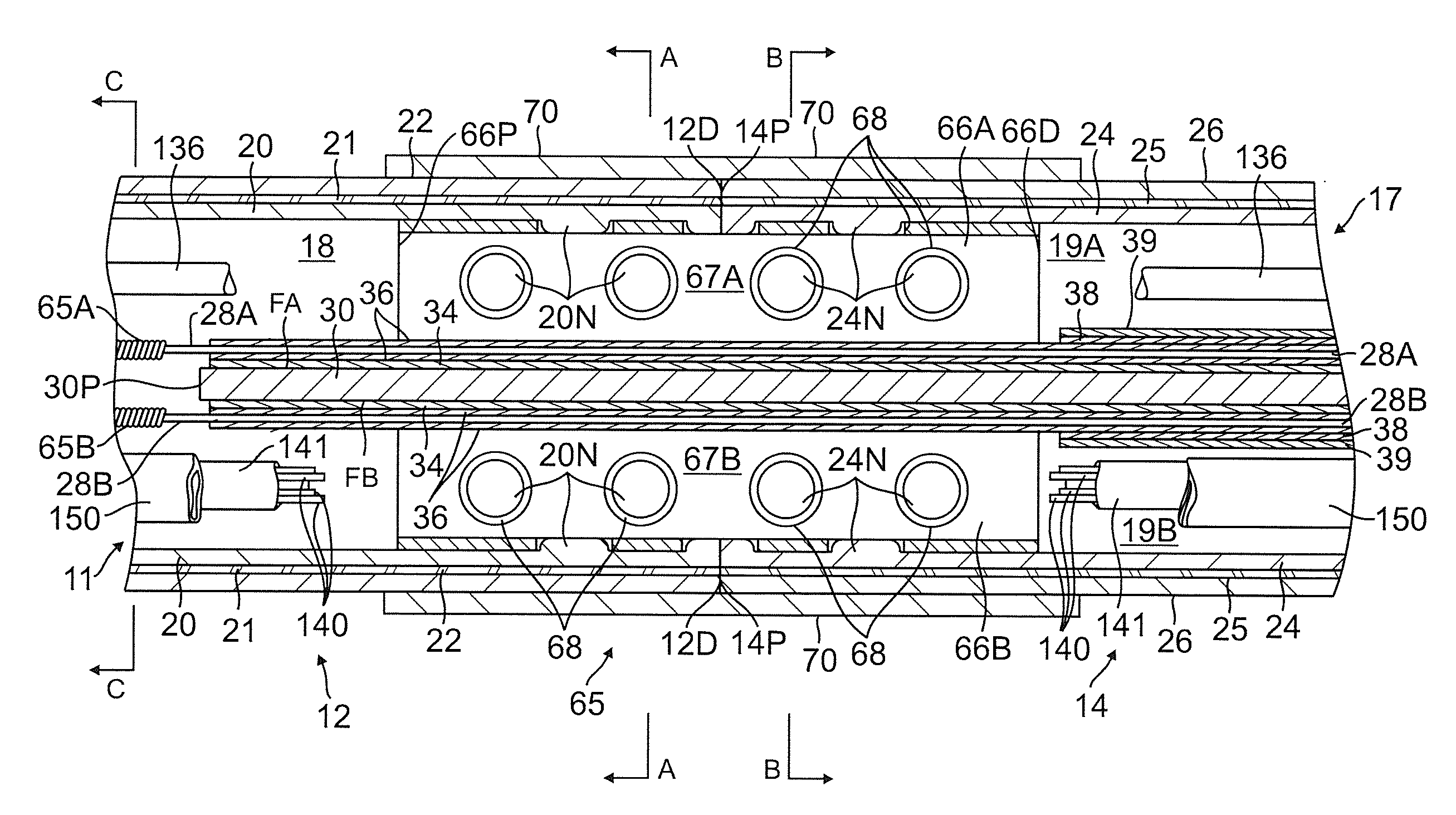
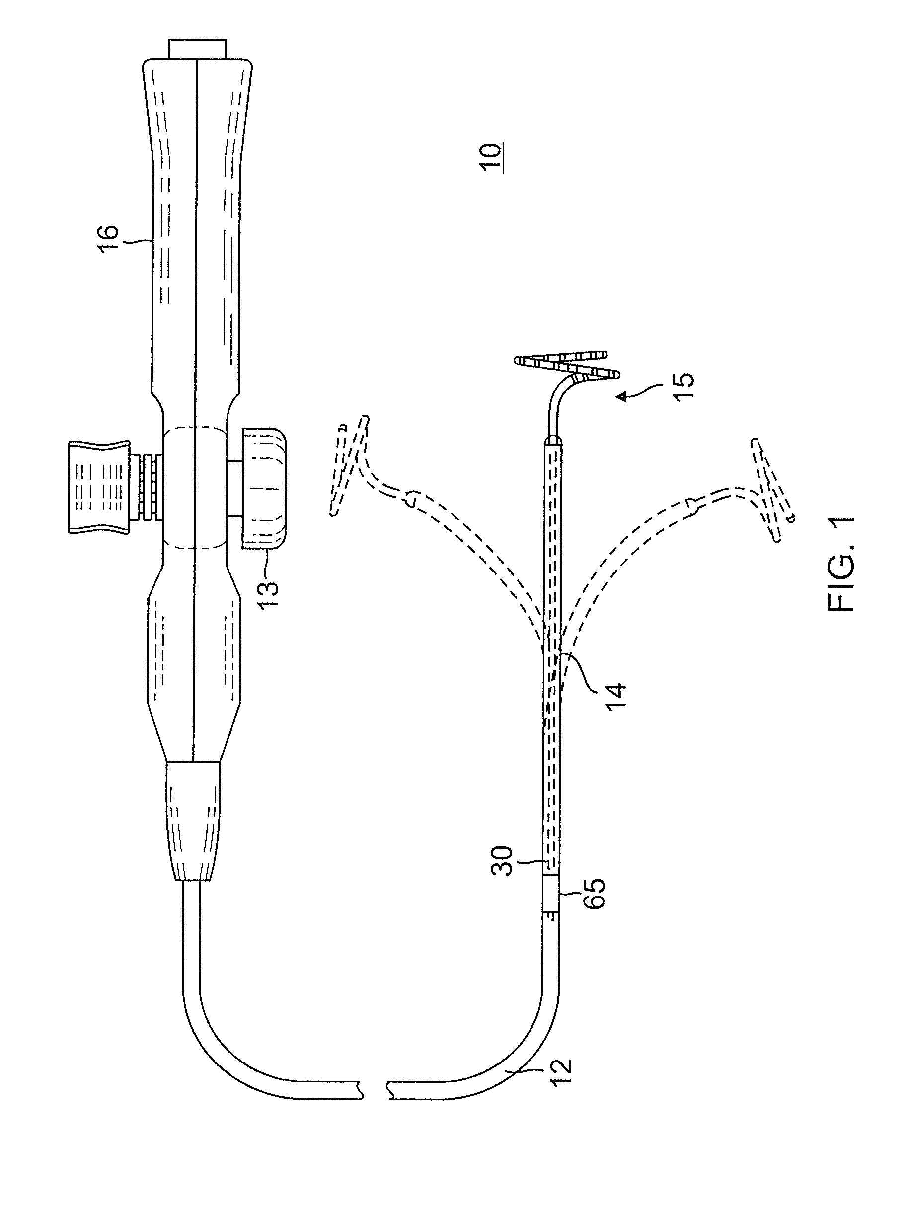
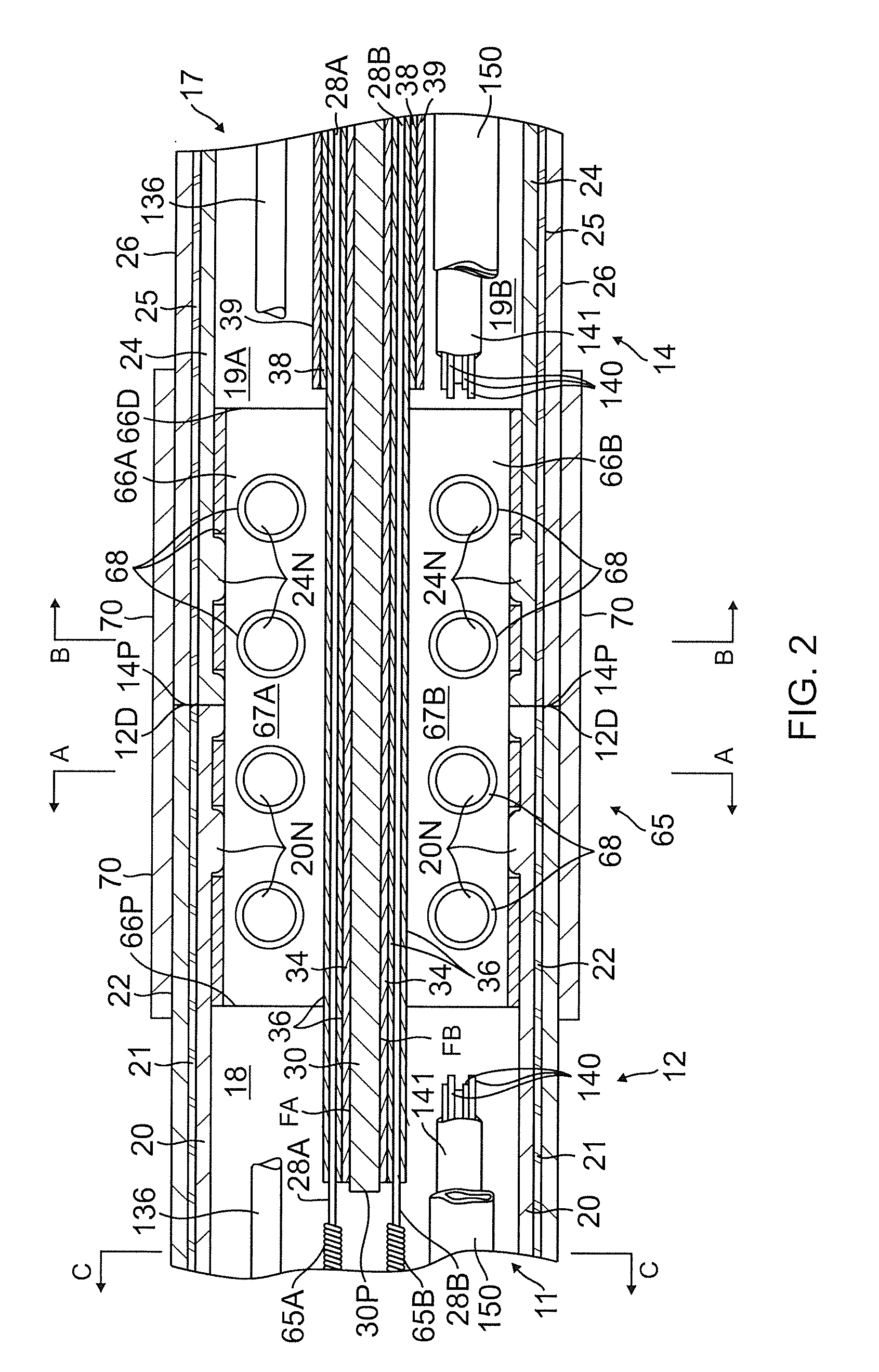
[0051]The present invention is directed to a catheter having a catheter body (or shaft) and a deflectable distal portion having an elongated flat beam or “blade” to effectuate precise on-plane bi-directional deflection while maximizing space within the catheter for components including lead wires, puller wires, cables, tubings and any other support members for advanced distal tip designs. With reference to FIG. 1, a catheter 10 in accordance with an embodiment of the present invention includes a catheter body 12, a deflectable distal section 14 distal of the catheter body, and a control handle 16 proximal of the catheter shaft. The deflectable section 14 has a tip assembly 15 having, for example, a lasso design with a generally circular main portion extending and oriented transversely from a distal end of the deflectable section 14. Bi-directional deflection is effectuated by user manipulation of an actuator 13 provided on the control handle 16 which moves a puller wire that extends...


PUM

PropertyMeasurementUnit
shore hardnessaaaaaaaaaa
diameteraaaaaaaaaa

Abstract

A catheter has a deflection beam with rectangular cross-section and a single continuous puller wire for predictable on-plane bi-directional deflection. The puller wire extends through spacers on opposite sides of the beam so the puller wire is maintained a predetermined separation distance from the beam surface. Tubular structures of the catheter body and the deflectable section are fused at a joint by C-shaped brackets mounted opposite surface of the beam to form a hollow body with holes into which thermoplastic materials covering the catheter body and the deflectable section can melt to form interlocking nodes. Elongated beam stiffeners can be mounted on the beam to provide different curve and deflection geometries.

Description

FIELD OF INVENTION[0001]The present invention relates to a medical device for use in the vessel of a patient for the purpose of diagnosing or treating the patient, such as mapping tissue and / or ablating tissue using radio frequency (RF) or other sources of energy. More particularly, the invention relates to a deflectable catheter having a flat beam for on-plane bi-directional deflection.BACKGROUND[0002]Electrode catheters have been in common use in medical practice for many years. They are used to stimulate and map electrical activity in the heart and to ablate sites of aberrant electrical activity. Atrial fibrillation is a common sustained cardiac arrhythmia and a major cause of stroke. This condition is perpetuated by reentrant wavelets propagating in an abnormal atrial-tissue substrate. Various approaches have been developed to interrupt wavelets, including surgical or catheter-mediated atriotomy. Prior to treating the condition, one has to first determine the location of the wav...

Claims


Application Information

Patent Timeline
Patent Type & Authority Applications(United States)
IPC IPC(8): A61M25/01
CPCA61M25/0147A61M25/0144A61M25/0138A61M25/0141A61M2025/015A61M25/0052A61M25/0051A61B18/1492A61M25/0009A61M25/0026A61M2207/00B29C63/0069B29C63/18B29C65/02B29K2995/0049B29L2031/7542
Inventor JIMENEZ, JOSEPADILLA, RICARDOSELKEE, THOMAS V.
Owner BIOSENSE WEBSTER (ISRAEL) LTD
Why Eureka
Try Eureka