Method and arrangement for preparing a charging plan

Active Publication Date: 2014-05-22
SANDVIK MINING & CONSTR OY
View PDF9 Cites 10 Cited by
  • Summary
  • Abstract
  • Description
  • Claims
  • Application Information

AI Technical Summary

Benefits of technology

The present invention provides a method and arrangement for producing drilling plans that take into account better conditions, resulting in more efficient and accurate tunneling. The method involves determining the location of hole ends and storing them in a memory. The pull-out of a round is determined based on the hole end locations and the topography of rock remaining after a round blast. A more appropriate charging plan for subsequent rounds is designed or modified based on the pull-out. The invention allows for changes in rock properties to be better managed, improving the efficiency of the entire tunneling process and reducing costs.

Problems solved by technology

In practice, in round blasting it has been found that even though the hole locations and the size and amount of blasting charges are dimensioned as well as possible on the basis of the known facts, the outcome of the blast does not, however, meet the planned design.
Typically, when detached material is removed after the blast, it may be found that the remaining rock surface deviates significantly from the theoretical surface that should have been created after the blast.
As a consequence, however, the efficiency of excavation deteriorates and this, in turn, causes quite significant additional costs.

Method used


Image

  • Method and arrangement for preparing a charging plan
  • Method and arrangement for preparing a charging plan
  • Method and arrangement for preparing a charging plan

Examples


Embodiment Construction

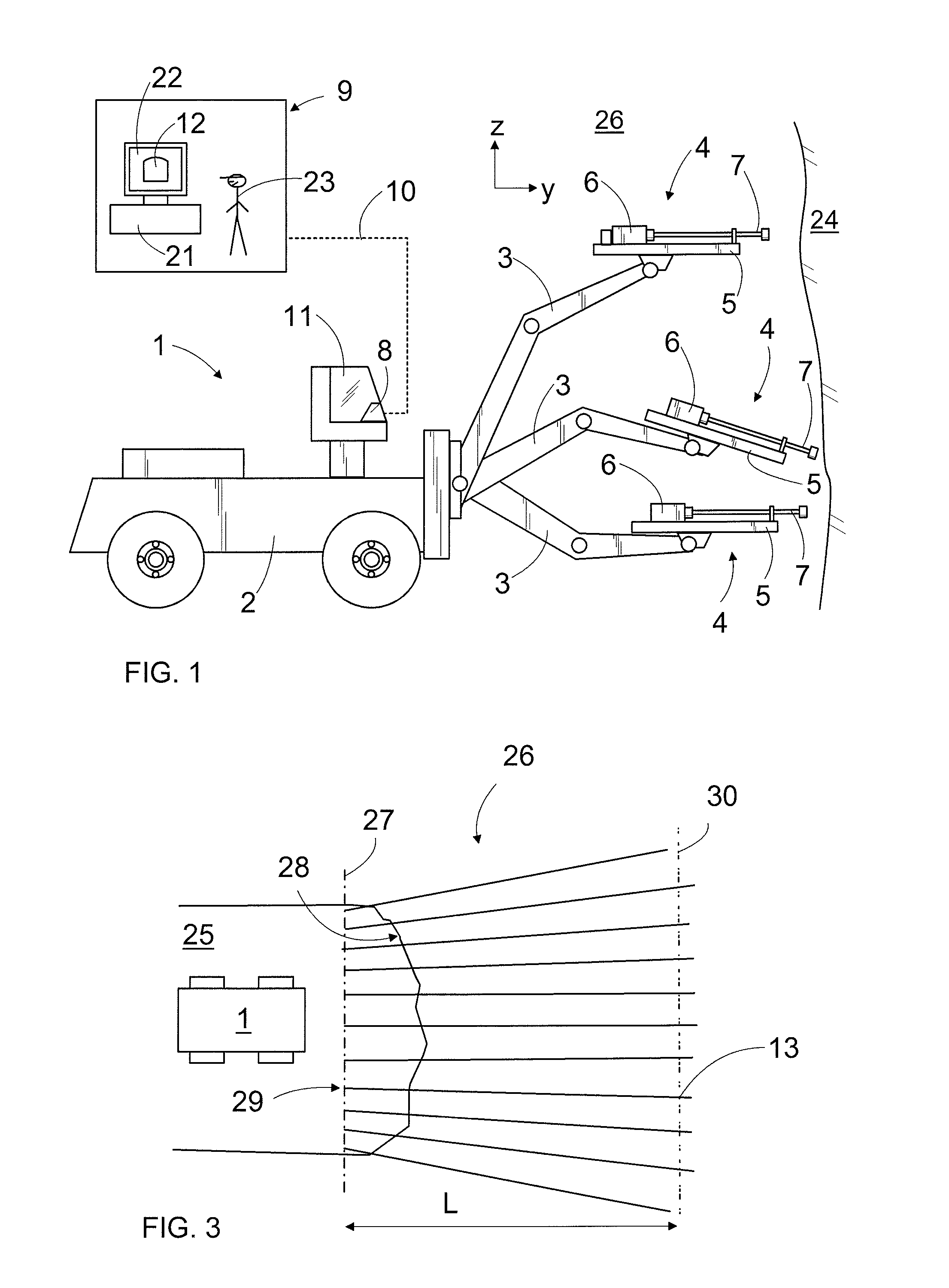
[0020]FIG. 1 shows a rock drilling apparatus 1 that comprises a movable carrier 2, one or more drilling booms 3 and drilling units 4 arranged to the drilling booms 3. The drilling unit 4 comprises a feed beam 5, that allows a rock drilling machine 6 to be moved by means of a feed device. Further, the drilling unit 4 includes a tool 7, by which impact pulses delivered by a percussion device of the rock drilling machine are transmitted to the rock to be drilled. The rock drilling apparatus 1 further comprises at least one control unit 8 configured to control actuators included in the rock drilling apparatus 1. The control unit 8 may be a computer or a corresponding device, and it may comprise a user interface including a display device as well as control means for giving commands and information to the control unit 8.

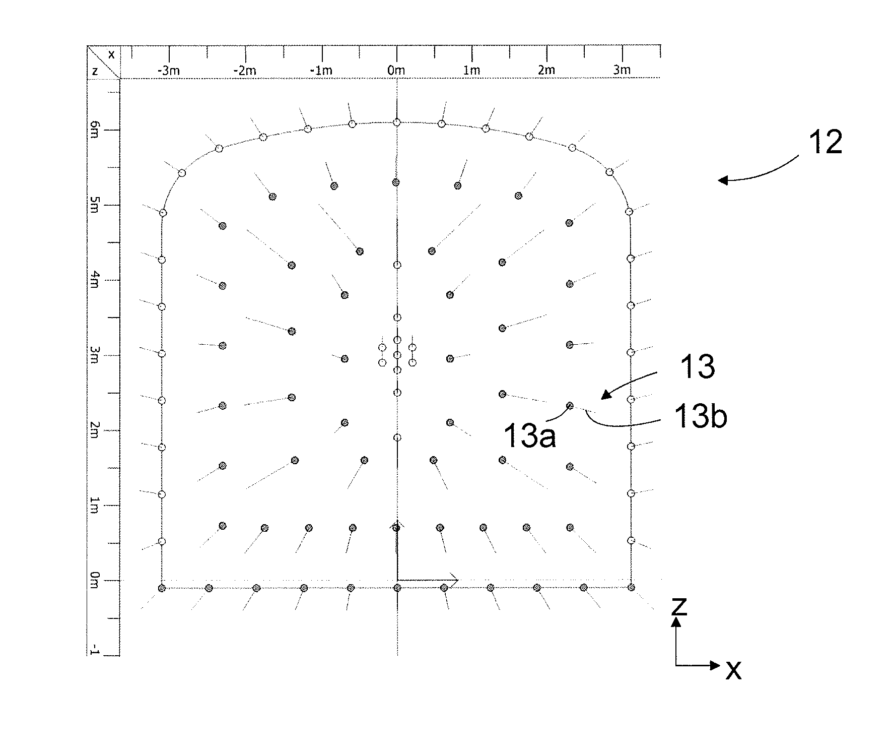
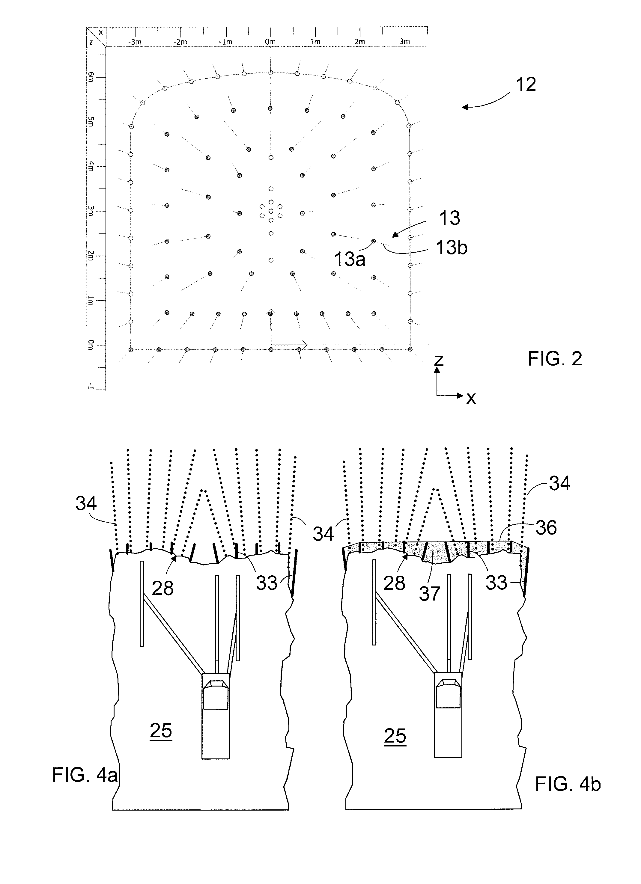
[0021]Typically, a drilling plan and an excavation profile taking into account the charging plan are created for each round. In the drilling plan, the locations of the ho...


PUM


Abstract

A method for preparing a charging plan for rock cavern excavation, in which plan drill hole locations for a round to be drilled in a tunnel face are determined in a predetermined coordinate system by using a drilling plan created by means of a computer-assisted design program. The method determines pull-out of a round on the basis of the locations of the hole ends and the topography of the rock remaining after a round blast, and designs or modifies a charging plan for a subsequent round on the basis of the thus determined pull-out.

Description

BACKGROUND OF THE INVENTION[0001]The invention relates to a method for preparing a charging plan for excavation of a rock cavern, the method comprising determining in advance at least drill hole locations in a pre-determined coordinate system for a round to be drilled into the rock cavern and creating a charging plan for the holes in the round by means of a computer-aided design program for blasting the round.[0002]The invention further relates to an arrangement for designing a charging plan for excavating a rock cavern with a rock drilling apparatus comprising one or more drilling booms having a rock drilling unit attached to it and a control unit for controlling the drilling comprising a computer, whereby at least locations of drill holes in a predetermined coordinate system has been defined in advance for a round to be drilled which arrangement comprises a computer with the computer assisted design program for designing the charging plan.[0003]Tunnels, underground storage silos a...

Claims


Application Information

Patent Timeline
IPC IPC(8): F42D3/04
CPCE21C37/16E21B7/022E21B7/025F42D3/00E21D9/006F42D3/04G05B19/18G06F30/00G06F30/20
Inventor MUONA, JOUKO
Owner SANDVIK MINING & CONSTR OY
Why Eureka
Try Eureka