Small Form-Factor Pluggable Optical Transceiver

Active Publication Date: 2014-05-22
SOURCE PHOTONICS
View PDF4 Cites 7 Cited by
  • Summary
  • Abstract
  • Description
  • Claims
  • Application Information

AI Technical Summary

Benefits of technology

[0015]Thus, the present invention relates to a two-cavity SFP optical transceiver module that can operate at two different temperatures in different regions of the module. Generally, the ambient temperature outside of the module, switch or switchboard is less than 55° C., but the temperature inside the module, switch or switchboard may exceed 75° C. The temperature of the extended nose (e.g., the tapered end or optical cavity of the transceiver) is the case temperature of the switch or switchboard, with which the optical subassembly (OSA) inside the optical cavity will be in thermal equilibrium. In addition, the temperature of the extended nose will be cooler than the temperature of the electrical (or back) portion of the transceiver, which is the temperature of the electronic parts inside the SFP casing. The present invention advantageously provides a two-part casing structure that can operate at different temperatures, having an extended nose

Problems solved by technology

However, overheating of the optical device cannot be eliminated.
Generally, overheating of the optical device occurs after connecting the SFP optical transceiver to the switchboard, since the electrical and optical devices of the SFP optical transceiver are completely enclosed in the switchboard.
The switchboard and the electrical devices of the SFP optical transceiver emit a significant amount of heat during normal

Method used


Image

  • Small Form-Factor Pluggable Optical Transceiver
  • Small Form-Factor Pluggable Optical Transceiver
  • Small Form-Factor Pluggable Optical Transceiver

Examples


embodiment 1

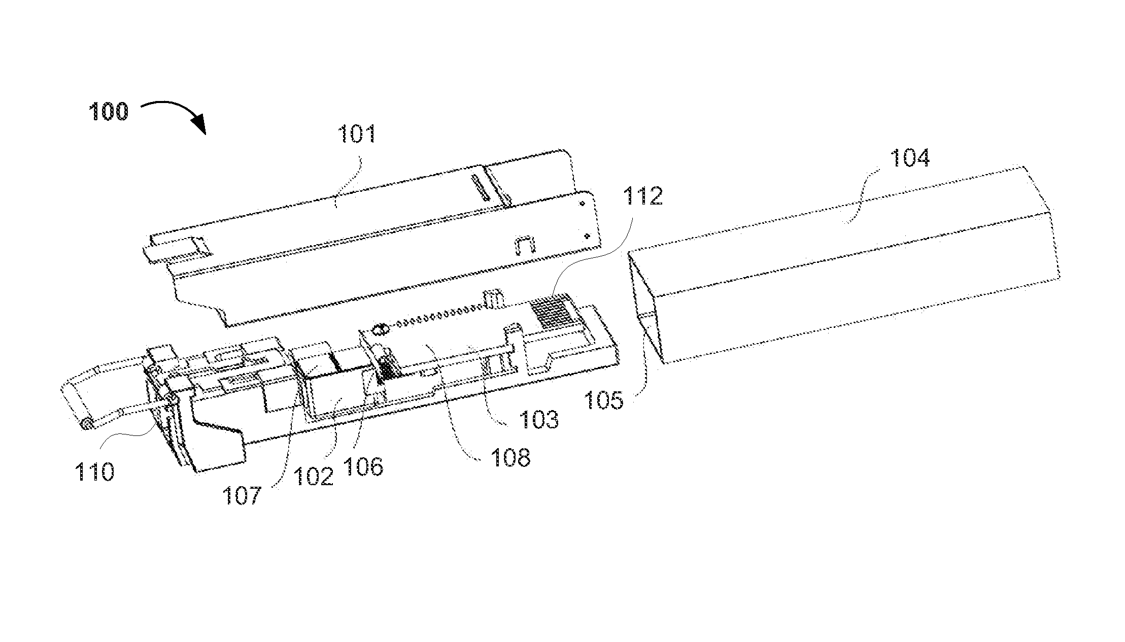
[0028]As shown in FIG. 1, a small form-factor pluggable (SFP) optical transceiver 100 comprises a casing 101 having an optical port 110 and an electrical port 112. The casing 101 is configured to accommodate optical devices 102 and electrical devices 103. The optical device 102 comprises a transceiver optical subassembly (TOSA) and a receiver optical subassembly (ROSA). The electrical devices 103 are located on a printed circuit board (PCB) on or near the bottom of the casing 101.

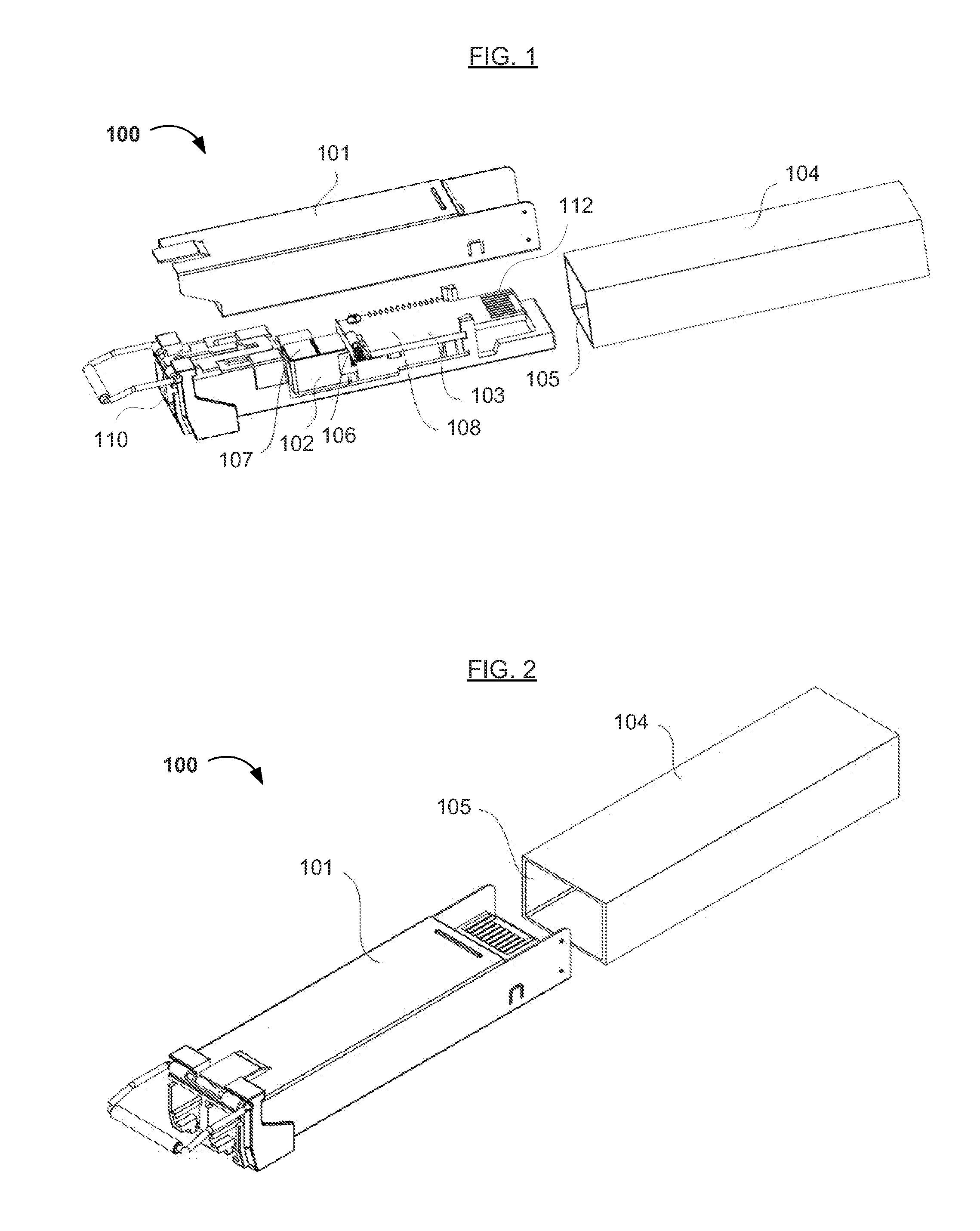
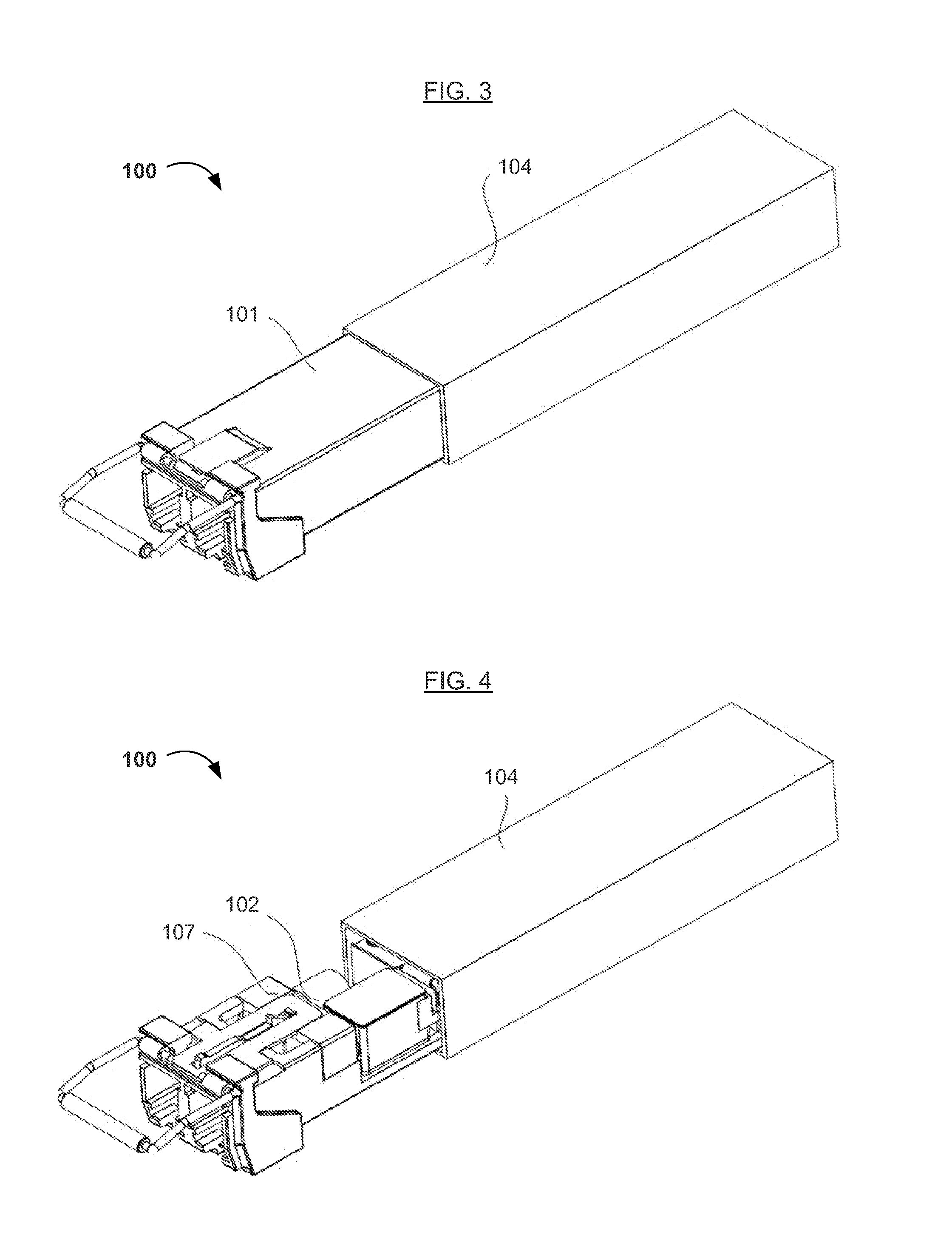
[0029]As shown in FIGS. 2-4, during normal operation, the casing 101 is connected to a switchboard 104 via a connector 105 located in the switchboard 104. As shown more clearly in FIG. 3, one portion of the casing 101 stays outside of the switchboard 104 after the casing 101 is inserted into the connector 105 located in the switchboard 104. More specifically, the electrical devices 103 inside the casing 101 and the portion of the casing 101 enclosing the electrical devices 103 stay inside the switchboard 10...

embodiment 2

[0031]As shown in FIGS. 5 and 6, based on or from Embodiment 1 above, an SFP optical transceiver 200 (or a casing 201 therefor) has a built-in (e.g., internal) isolator 206. The isolator 206 is configured to divide the transceiver 200 (or casing 201) into a first cavity 207 close to or facing the optical port 210 and a second cavity 208 close to or facing the electrical port 212. The optical devices (not shown) are located in the first cavity 207, and the electrical devices (not shown) are located in the second cavity 208. After the transceiver 200 (or casing 201) is divided into two relatively independent cavities via the isolator 206, the portion 208 containing the electrical devices having a relatively high temperature is isolated from the portion 207 containing the optical devices. Heat produced by the electrical device portion 203 having a high temperature during normal operation can be blocked from being transferred to the cavity 207 where the optical devices are located, resu...

embodiment 4

[0038]The casing 201 of Embodiment 4, as shown in FIG. 6 for an SFP optical transceiver 200 is similar to other various casings.

[0039]Referring to FIG. 6, the casing 201 of FIG. 6 has a de-latching unit 215 on a top surface (e.g., face), in which the de-latching unit 215 is configured to latch the casing 201 (of FIG. 6) and the switchboard 204. Alternatively, the de-latching unit 215 releases the casing 201 (of FIG. 6) from the switchboard 204. In Embodiment 4, the de-latching unit 215 is located over or on top of the second cavity 208. When the second cavity 208 is inserted into the switchboard 204 and the first cavity 207 remains outside the switchboard, the casing 201 and the switchboard 204 are steadily connected.

[0040]In addition to keeping the first cavity 207 outside the switchboard 204, air holes 209 are located in the cover and base of the casing 201 (of FIG. 6) corresponding to the first cavity 207 to further increase heat dissipation efficiency. The air holes 209 run thro...


PUM


Abstract

A small form-factor pluggable (SFP) optical transceiver includes a casing configured to accommodate optical and electrical devices. During normal operation, the casing is connected to a switchboard via a connector in the switchboard, and the optical devices are outside the switchboard, thereby exposing optical devices sensitive to high temperature to the outside air, reducing the operational temperature of the optical device portion relative to the heated portion inside the switchboard. Thus, the present SFP optical transceiver advantageously improves operational performance and extends the life of the device. Also, the present SFP optical transceiver having the optical device portion outside the switchboard advantageously improves the cooling performance for the optical device portion.

Description

CROSS REFERENCE TO RELATED APPLICATION[0001]This application claims the benefit of Chinese Patent Application No. 201210471478.3, filed on Nov. 20, 2012, which is incorporated herein by reference as if fully set forth herein.FIELD OF THE INVENTION[0002]The present invention generally relates to the field of optoelectronic communications and devices therefor, and particularly to an optical transceiver. More specifically, embodiments of the present invention pertain to a small form-factor pluggable (SFP) optical transceiver, particularly circuits, devices, and method(s) of making and / or using the same.DISCUSSION OF THE BACKGROUND[0003]A small form-factor pluggable (SFP) optical transceiver, generally defined by an applicable MSA standard, provides bidirectional data transmission in optical communications. Generally, a conventional SFP optical transceiver comprises (i) a casing, (ii) electrical devices, such as printed circuit boards (PCB), chips, etc., and (iii) optical devices, such ...

Claims


Application Information

Patent Timeline
IPC IPC(8): G02B6/42
CPCG02B6/4273G02B6/36G02B6/4246G02B6/4292
Inventor HEIMBUCH, MARKWAINWRIGHT, WAYNE
Owner SOURCE PHOTONICS
Why Eureka
Try Eureka