
Method for correcting the voltage measured across the terminals of a sensor

a technology of voltage measurement and sensor terminal, applied in the field of sensors, can solve problems such as non-linear variability of error, measurement error, and systematic undesirable error

Active Publication Date: 2014-05-29
SAFRAN ELECTRONICS & DEFENSE
View PDF2 Cites 10 Cited by
  • Summary
  • Abstract
  • Description
  • Claims
  • Application Information

AI Technical Summary

Benefits of technology

The invention allows for compensating for errors in sensors that are connected to a computer. These errors can occur because of the output impedance of the sensor. The invention can also correct subsequent voltage measurements.

Problems solved by technology

Now, it is known that, when a sensor which may be assimilated to an equivalent voltage generator in series with the source impedance is connected to a digital computer having finite input impedance, a measurement error occurs if the ratio between the output impedance of the sensor and the input impedance of the computer is not negligible.
This undesirable error occurs systematically and directly depends on the type of sensor and on the relevant computer.
In this case, the equivalent series impedance variation resulting from the measurement point generates an error which varies non-linearly depending on the measurement point.
This non-linear error may theoretically be compensated but the required compensation strongly complicates the algorithm for converting the measurement into a physical quantity at the digital computer, which most often leads to the use of approximation functions which simplify this algorithm at the expense of the attained accuracy.
For certain sensors, the error induced by these differences in impedance may be significant, reaching through to the maximum total error which is tolerated for the relevant acquisition chain (set to 1% for example).
This impedance error will thus be added to the other inaccuracies which generally affect an acquisition chain.
Therefore it is not possible to apply error compensation a priori since the error will vary according to the sensor used.

Method used


Image

  • Method for correcting the voltage measured across the terminals of a sensor
  • Method for correcting the voltage measured across the terminals of a sensor
  • Method for correcting the voltage measured across the terminals of a sensor

Examples


Embodiment Construction

[0041]As indicated earlier, the invention relates to the general field of sensors and more particularly relates to the compensation of measurement errors related to the output impedance of a sensor.

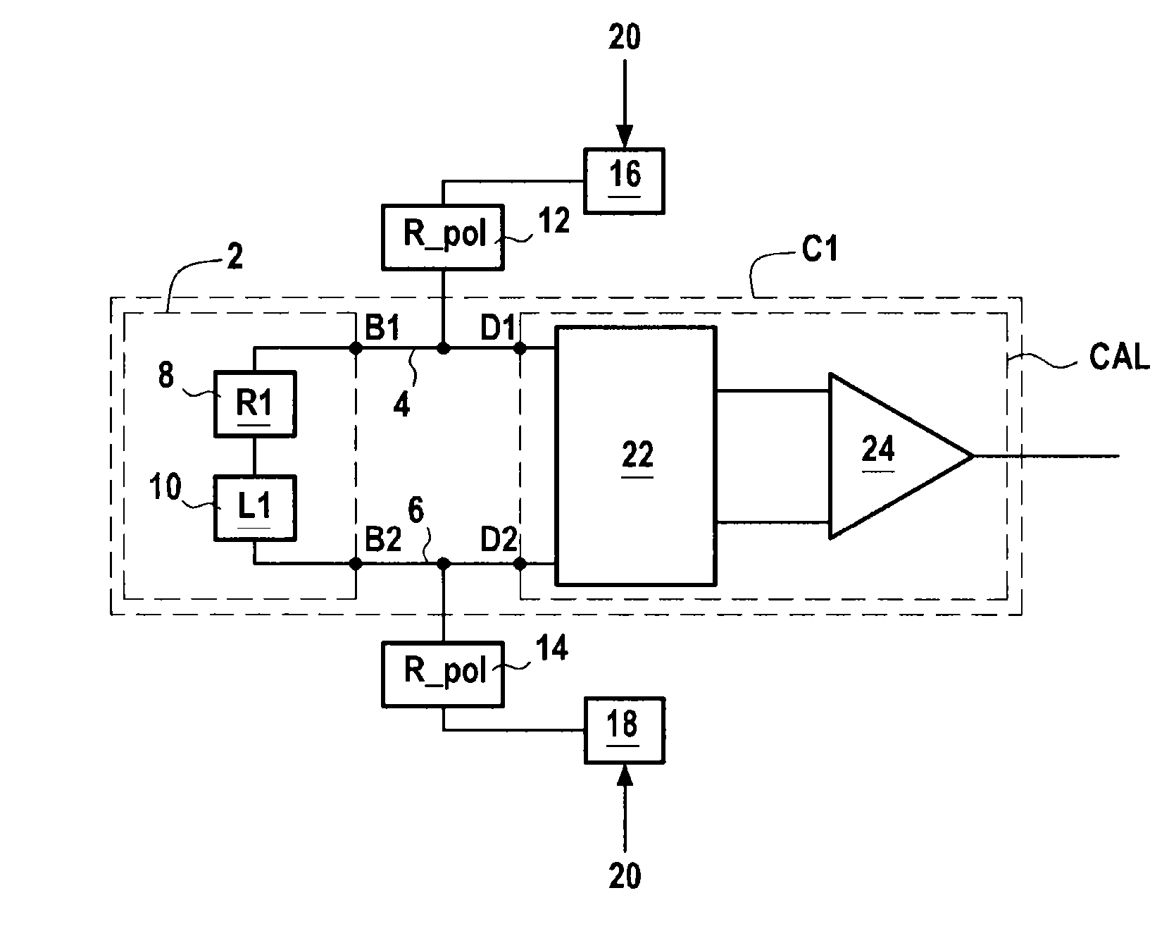
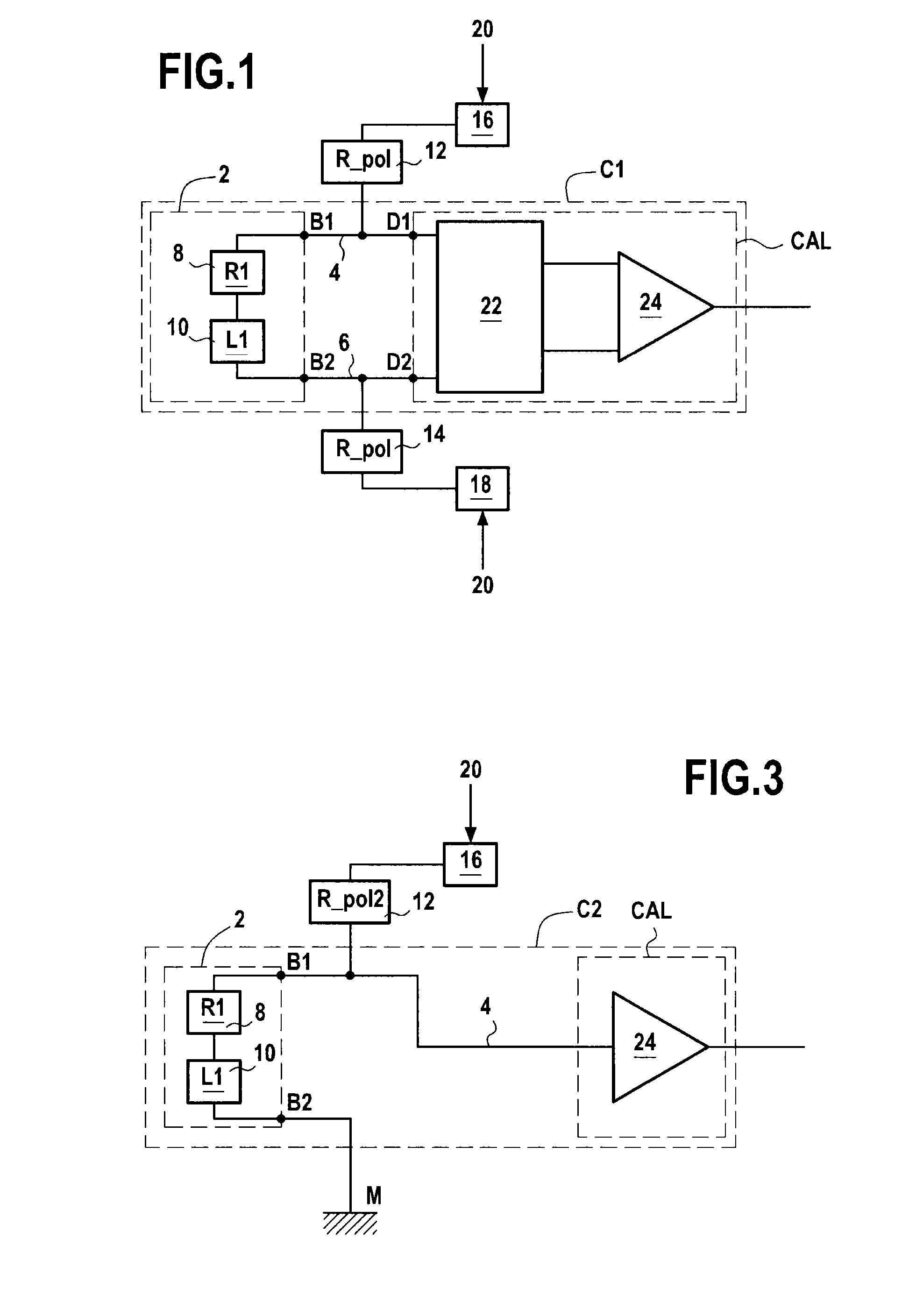
[0042]A first embodiment of the invention is now described with reference to FIG. 1. In this particular embodiment, the invention allows digital compensation of the error caused by the series impedance of a resistive sensor. More particularly, FIG. 1 illustrates, in its environment, an example of an acquisition chain C1 in which it is intended to correct the measurement error induced by the impedances of a sensor and of a digital computer.

[0043]More specifically, this acquisition chain C1 comprises a sensor 2, a digital computer CAL, and two conducting lines 4 and 6 respectively connecting both terminals B1 and B2 of the sensor 2 to the two terminals D1 and D2 of the digital computer CAL.

[0044]The sensor 2 may be assimilated to an equivalent voltage generator 10 placed in series with a re...


PUM


Abstract

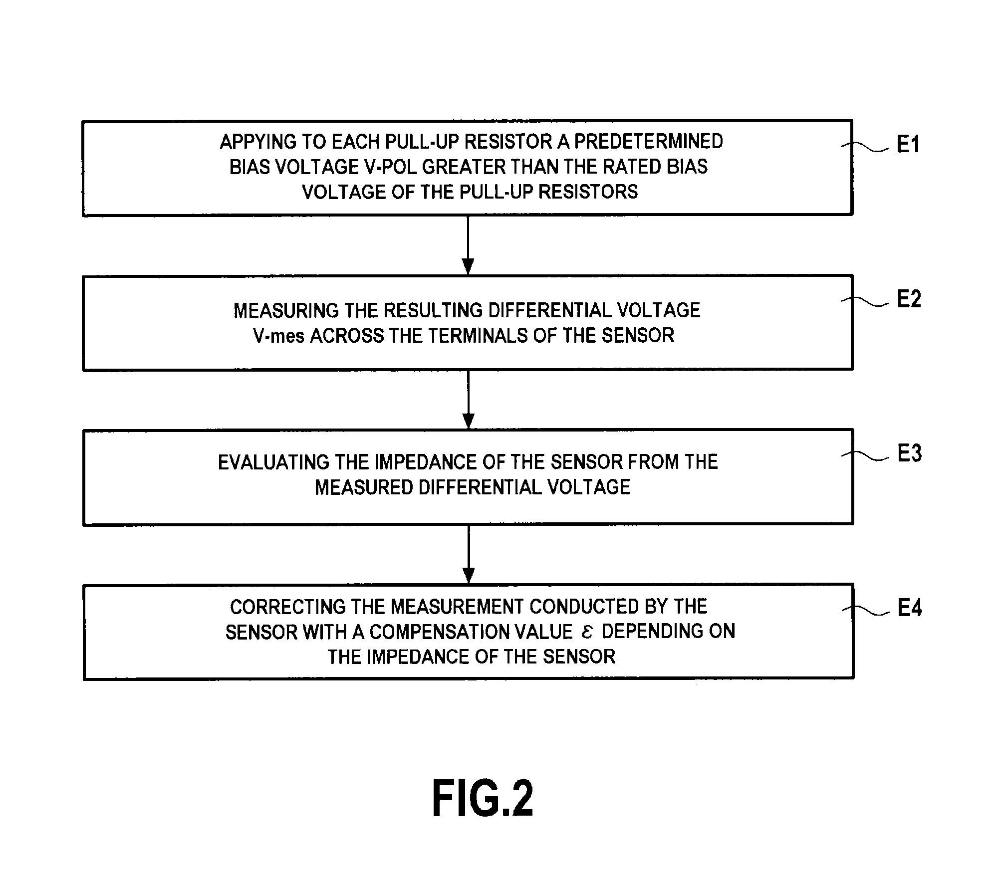
A method for correcting measurement of a voltage across output terminals of a sensor, the sensor configured to be assimilated with an assembly including a generator and a series resistance, each of the output terminals being respectively connected to a pull up / down resistor. The method includes: evaluating the series resistance of the sensor, including measuring first and second voltages across the output terminals when first and second bias voltages are applied on each pull up / down resistor; evaluating the series resistance from the first and second voltages; and correcting, from the series resistance, a voltage measured across the output terminals of the sensor to infer therefrom a corresponding voltage generated by the generator.

Description

BACKGROUND OF THE INVENTION[0001]The invention relates to the general field of sensors, such as for example temperature, pressure, displacement sensors, etc.[0002]More particularly, it relates to the compensation of measurement errors related to the output impedance of a sensor.[0003]The invention has a preferential but non-limiting application in the aeronautical field, where many sensors are used (on-board an aircraft for example).[0004]In practice, a sensor is generally connected to a digital computer which is responsible for receiving and processing measurement data transmitted from the sensor, the sensor and the digital computer thus being part of an acquisition chain.[0005]Now, it is known that, when a sensor which may be assimilated to an equivalent voltage generator in series with the source impedance is connected to a digital computer having finite input impedance, a measurement error occurs if the ratio between the output impedance of the sensor and the input impedance of ...

Claims


Application Information

Patent Timeline
Patent Type & Authority Applications(United States)
IPC IPC(8): G01R35/00
CPCG01R35/005G01D3/00G01D3/036G01L1/2262
Inventor LACOMBE, BERTRANDGENESTE, NICOLASRAES, MARC
Owner SAFRAN ELECTRONICS & DEFENSE
Learn More