Method in a Base Station of a Communication System for Making a Handover Decision, Base Station, Computer Programs, and Computer Program Products

a communication system and base station technology, applied in the field of handover, can solve the problems of increasing unmotivated coupling between system information and data coverage, affecting the handover process, and affecting the handover process, and achieve the effect of improving handover

Active Publication Date: 2014-05-29
TELEFON AB LM ERICSSON (PUBL)
View PDF7 Cites 42 Cited by
  • Summary
  • Abstract
  • Description
  • Claims
  • Application Information

AI Technical Summary

Benefits of technology

[0010]An object of the invention is to improve handover, particularly in view of having dynamically reconfigurable cells.

Problems solved by technology

This is a waste of energy since typically a user equipment in a given location and direction is measuring the downlink pilot signal only parts of the time.
However, as the performance of current radio communication system systems is improved, including novel features such as coordinated multi-point (CoMP), multi-carrier, and multi-hop support this coupling between system information and data coverage becomes increasingly unmotivated.
Further, with beam-forming, MIMO (Multiple-input, multiple output), multi-carrier, CoMP, multi-radio access technologies, and reconfigurable antenna systems the cell concept becomes unclear and the traditional interpretation of the cell concept is being questioned.
However, current mobility solutions are not designed for radio communication systems wherein the cells may be dynamically re-configured.
If considering the cells to be dynamic and user equipment specific, mobility issues will arise.
In case the non-serving candidate cell is capable of beam-forming a data transmission towards the particular user equipment, then it is not possible for the user equipment to in advance determine the quality of the signal after handover, as the use of the multiple antenna elements (enabling the beam-forming) of the candidate cell cannot be predicted by the user equipment.

Method used


Image

  • Method in a Base Station of a Communication System for Making a Handover Decision, Base Station, Computer Programs, and Computer Program Products
  • Method in a Base Station of a Communication System for Making a Handover Decision, Base Station, Computer Programs, and Computer Program Products
  • Method in a Base Station of a Communication System for Making a Handover Decision, Base Station, Computer Programs, and Computer Program Products

Examples


first embodiment

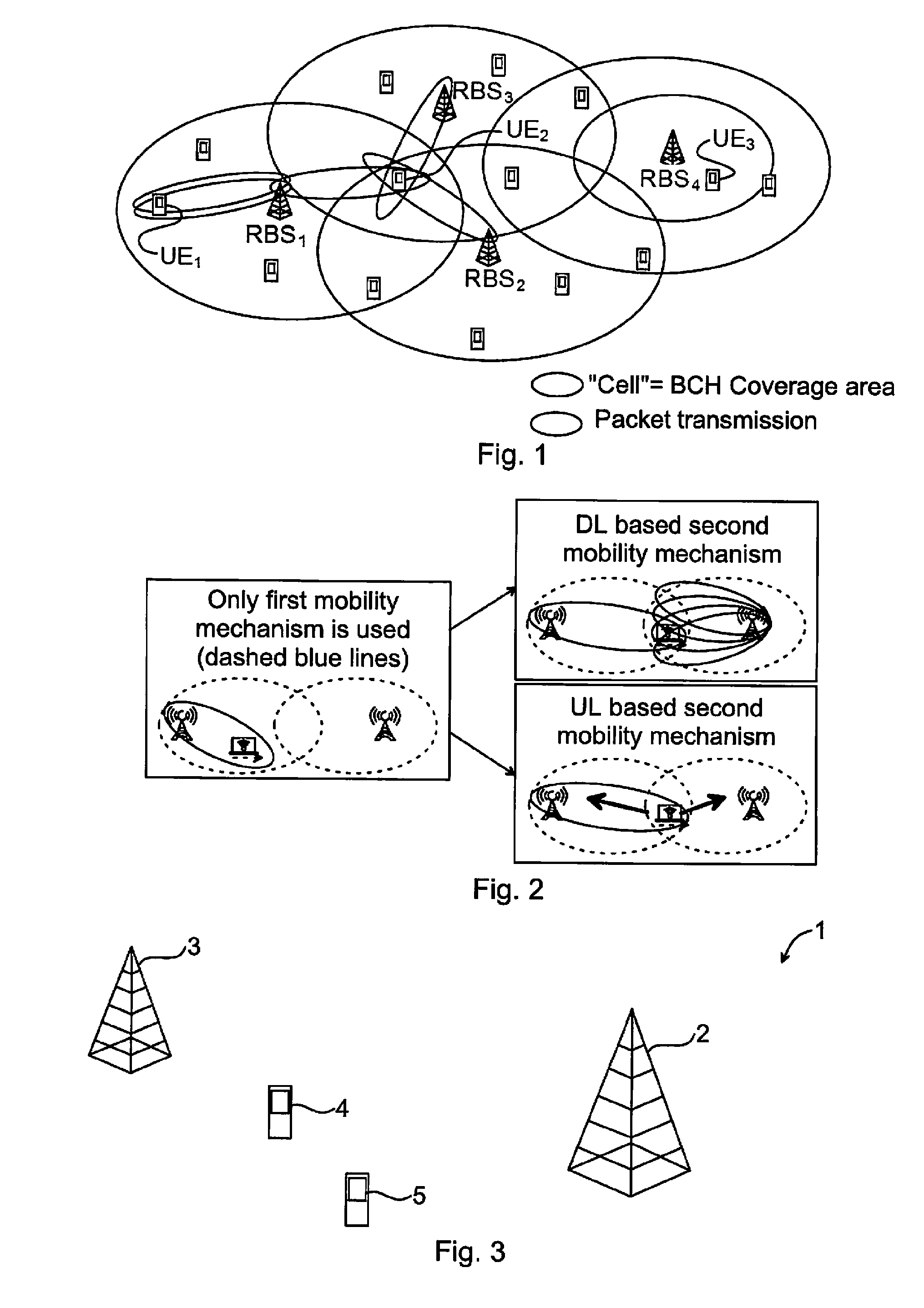
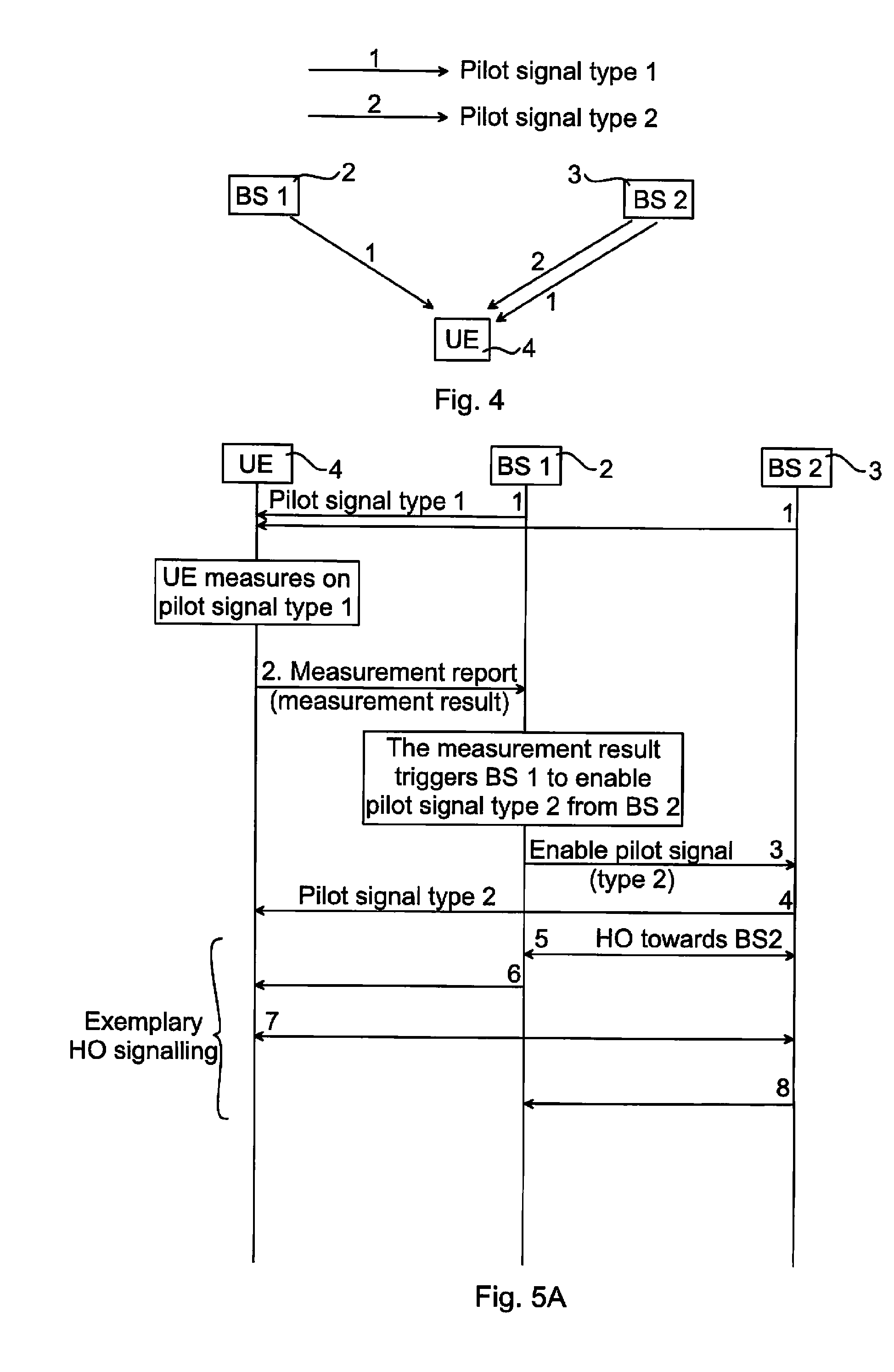
[0041]FIG. 4 illustrates schematically pilot signaling of the invention. The first base station 2 is the base station currently serving the user equipment 4, and the second base station 3 is a possible candidate or target base station. The first base station 2 and the second base station 3 both transmit a first type of pilot signal (indicated in the figure by arrows denoted 1) used for mobility purposes. The user equipment 4 receives these pilot signals, makes measurements on them and reports the measurements to the first base station 2. Based on the downlink pilot signal measurements performed by the user equipment 4 and reported e.g. to the first base station 2, a second type of pilot signal is transmitted by the second base station 3.

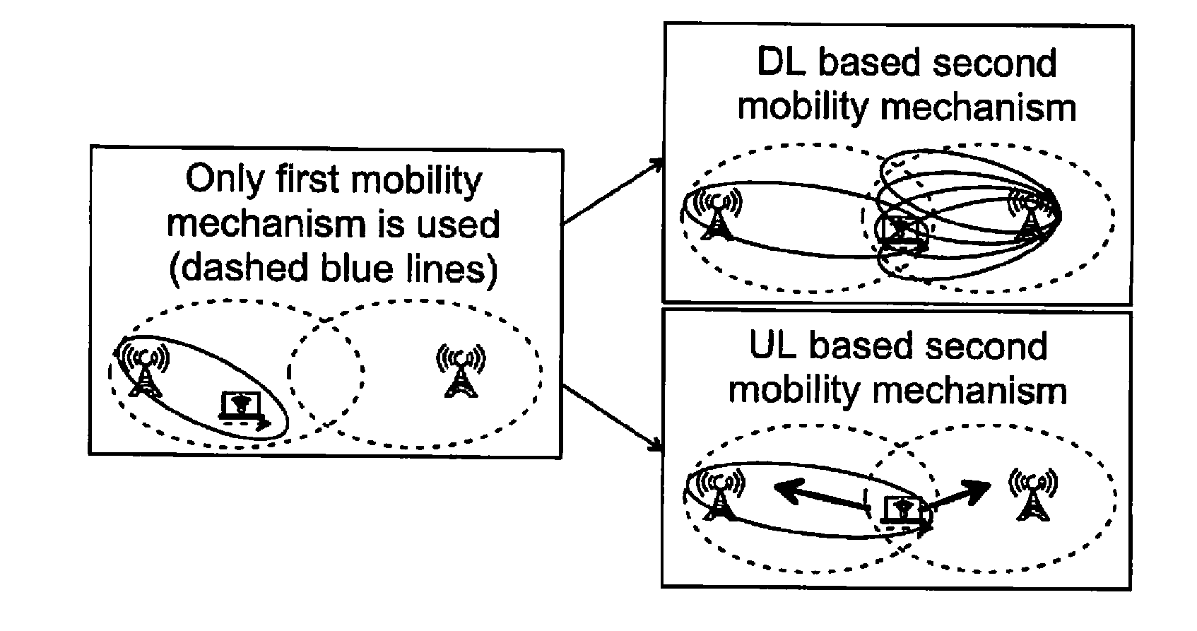
[0042]FIG. 5A is a sequence diagram illustrating exemplary signaling between nodes of the communication system 1 for the embodiment of FIG. 4. This embodiment can be seen as a downlink based second mobility mechanism (refer also to FIG. 2).

[0043]The ...

second embodiment

[0046]FIG. 6 illustrates schematically pilot signaling of the invention. The first base station 2 is again the base station currently serving the user equipment 4, and the second base station 3 is the target base station. The first base station 2 and the second base station 3 both transmit a first type of pilot signal (indicated in the figure by arrows denoted 1) used for mobility purposes. The user equipment 4 receives these pilot signals and makes measurements on them and reports the measurements to the first base station 2. Based on this measurement, the first base station 2 requests a second type of pilot signal from the user equipment 4.

[0047]FIG. 7A is a sequence diagram illustrating exemplary signaling between nodes of a communication system for the embodiment of FIG. 6. This embodiment can be seen as an uplink based second mobility mechanism (refer also to FIG. 2).

[0048]The first base station 2 and the second base station 3 transmit the first type of pilot signal (arrows den...


PUM


Abstract

The invention relates to a method (20) in a base station (2, 3) of a communication system (1) for making a handover decision, the communication system 1 comprising a user equipment (4, 5). The method (20) comprises the steps of: performing (21) a first type of mobility mechanism for the user equipment (4, 5), and upon the first type of mobility mechanism fulfilling a criterion: configuring (22) a second type of mobility mechanism for the user equipment 4, 5, and making (23) a handover decision for the user equipment (4, 5) based on the second type of mobility mechanism. The invention also relates to a base station, computer programs and computer program products.

Description

FIELD OF THE INVENTION [0001]The invention relates generally to the field of handover, and in particular to handover related signaling.BACKGROUND OF THE INVENTION[0002]Handover measurements are performed in a similar way in all present cellular radio communication systems. A user equipment measures on downlink pilot signals transmitted by neighboring base stations, and compares with a downlink pilot signal received from the serving base station that the user equipment is currently connected to. Quantities measured are typically different means of signal strength (e.g. Reference Signal Received Power, RSRP) and signal quality (e.g. Reference Signal Received Quality, RSRQ).[0003]An instruction with a list of neighboring base stations for the user equipment to measure on may be sent from the cellular radio communication system and is typically based on the current location (cell) of the user equipment. The user equipment may alternatively by itself find the downlink pilot signals sent ...

Claims


Application Information

Patent Timeline
Patent Type & Authority Applications(United States)
IPC IPC(8): H04W36/00H04W36/32
CPCH04W36/32H04W36/00837H04W36/0085H04W36/0011H04W36/0088
Inventor WALLENTIN, PONTUSERIKSSON, ERIKFRENGER, PAL
Owner TELEFON AB LM ERICSSON (PUBL)
Why Eureka
Try Eureka