Continuous passive motion apparatus

a passive motion and continuous technology, applied in the field of ##uous passive motion machines, can solve the problems of large machines and cumbersomeness, and achieve the effects of reducing the number of machines, facilitating rehabilitation, and facilitating rapid and easy disassembly

Inactive Publication Date: 2014-05-29
HOFFMAN LESLIE
View PDF3 Cites 12 Cited by
  • Summary
  • Abstract
  • Description
  • Claims
  • Application Information

AI Technical Summary

Benefits of technology

[0010]Although quite stable in use, the assembly can be quickly and easily dismantled and broken down into functional assemblies that can be accommodated in a duffel-bag or the like.
[0012]An electronic control console is available for the patient to set and modify normal motion parameters. Additional functionality is incorporated to protect and improve the comfort of the patient. For example, in the event of a loss of power the carriage and joint return to known and defined home position. It is expected that this home position will result in the leg being generally horizontal.

Problems solved by technology

Initially such machines were very large and cumbersome, and they were typically attached to a bed or integrated with the patient bed in a manner that prevented portability of the therapy device.

Method used


Image

  • Continuous passive motion apparatus
  • Continuous passive motion apparatus
  • Continuous passive motion apparatus

Examples


Embodiment Construction

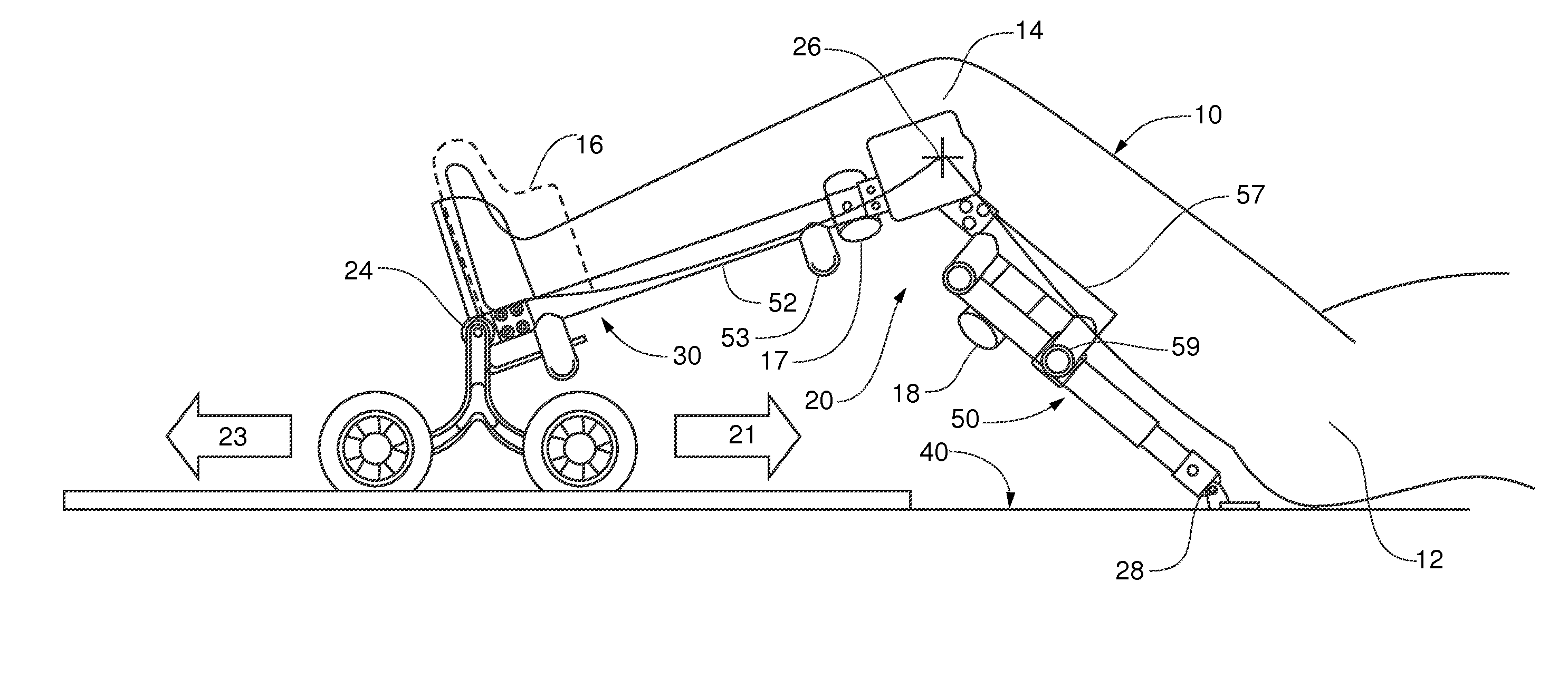
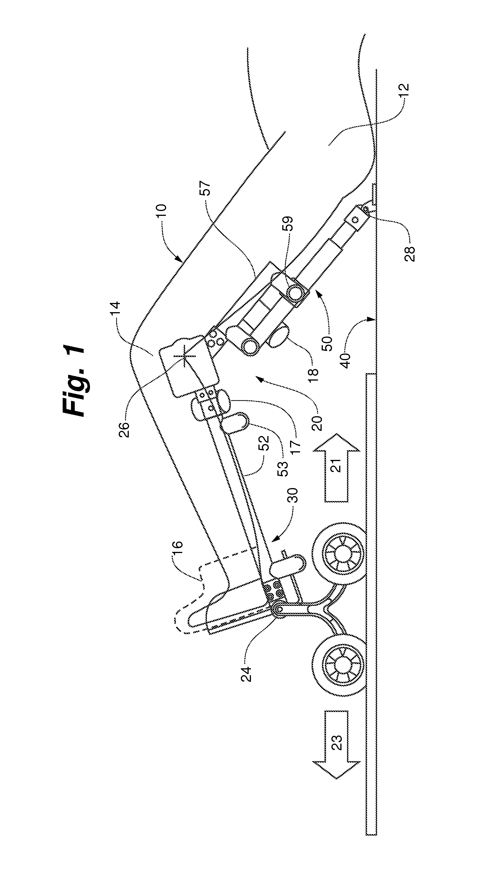
[0024]FIG. 1 shows the continuous passive motion (CPM) device 20 in use by a patient 10. The CPM device or machine can be readily broken down into several subassemblies such as a Foot Frame Assembly (FFA) 30, a Track Pad Assembly (TPA) 40, and a Leg Frame Assembly (LFA) 50.

[0025]In use the patient 10 anchors and stabilizes the TPA 40 by putting the hips 12 on a portion of the TPA 40 thereby transferring weight to the CPM device 20 fixing the motion of the machine to the bed (not seen) and the patient's knee joint 14. With CPM device 20 fixed with respect to the hips 12 the Foot Frame Assembly 30 may move in a first direction 21 toward the hips 12 and a second direction 23 away from the patient's hips. These two motions can be controlled and result in therapeutic flexion of the knee joint 14.

[0026]To achieve these motions the CPM device 20 includes a foot frame pivot axis 24, a knee joint pivot axis 26 and a track pad pivot axis 28. The controlled motion is driven by a motor and gear...


PUM


Abstract

An easily dismantled continuous passive motion system for rehabilitating a knee joint with the drive applied directly to the knee joint portion of the device.

Description

CROSS REFERENCE[0001]This application is a utility case conversion of U.S. Provisional Application 61 / 711,315, filed Oct. 9, 2012 and this application claims the benefit of this provisional filing. This provisional application is hereby incorporated by reference in its entirety.BACKGROUND OF THE INVENTION[0002]Continuous passive motion (CPM) machines are designed to flex a joint through a controlled range of motion to help patients rehabilitate and recover from surgeries or other treatments on the joint.[0003]Initially such machines were very large and cumbersome, and they were typically attached to a bed or integrated with the patient bed in a manner that prevented portability of the therapy device.[0004]More recently unitary but otherwise portable devices such as the OptiFlex by Chattanooga Group (a brand of DJO Global, Inc., Guildford, Surrey, England) have been introduced to provide a compact CPM machine to provide CPM therapy outside the hospital setting.[0005]In spite of these...

Claims


Application Information

Patent Timeline
Patent Type & Authority Applications(United States)
IPC IPC(8): A61H1/00
CPCA61H1/00A61H1/0259A61H1/024A61H2201/0176A61H2201/0192A61H2201/1215A61H2201/1642A61H2201/1671A61H2201/5038A61H2203/0456
Inventor HOFFMAN, LESLIE
Owner HOFFMAN LESLIE
Why Eureka
Try Eureka