Leadless implantable device delivery apparatus

a technology of implantable devices and delivery devices, which is applied in the field of medical devices and devices for implantation, can solve the problems of increasing the risk of complications and general abandonment of devices, and achieves the effect of minimizing the effect of the implantation procedur

Active Publication Date: 2014-05-29
BIOTRONIK SE & CO KG
View PDF3 Cites 120 Cited by
  • Summary
  • Abstract
  • Description
  • Claims
  • Application Information

AI Technical Summary

Benefits of technology

[0007]At least one embodiment of the invention provides a leadless implantable device delivery apparatus that for example enables testing of an implantation site before permanent implantation and enables secure attachment of a leadless implantable device at the site while minimizing effects of the implantation procedure.
[0011]During delivery of the leadless implantable device, rotation in one direction imparts rotational force onto the anchor element coupled with the implantable device, wherein the rotational force is transmitted from the press-fit coupling element to the proximal portion of the adapter to the distal portion of the adapter to the implantable device to the anchor. During release, the press-fit coupling element is disengaged from a corresponding cavity in the delivery sheath, which disables rotational forces from travelling through or otherwise along the adapter, and which ensures that no disengagement of the anchor occurs when the adapter is uncoupled from the implantable device.

Problems solved by technology

In addition, explantation of electrode leads that have been implanted for long periods of time increases the risk of complications.
However, the disadvantages are that the leadless implantable devices currently implanted are difficult to position at an optimal implantation site, and once implanted, generally with hooks, these types of devices are generally abandoned when their battery life is exhausted since their implantation is intended to be permanent.

Method used


Image

  • Leadless implantable device delivery apparatus
  • Leadless implantable device delivery apparatus
  • Leadless implantable device delivery apparatus

Examples


first embodiment

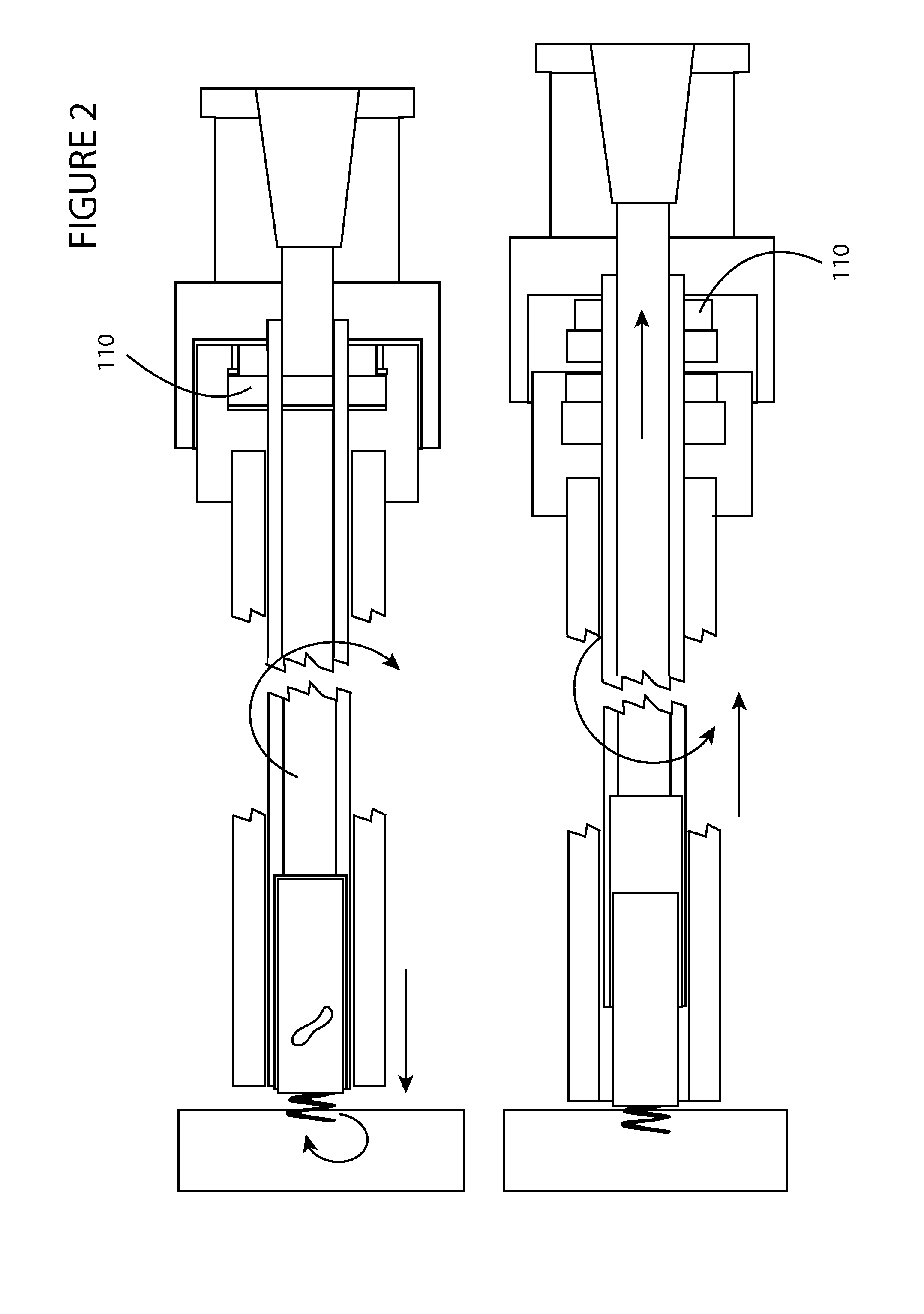
[0023]FIG. 2 shows a side view of the invention shown in FIG. 1 during delivery of an implantable medical device and during release of the implantable medical device. During delivery, rotation in one direction imparts rotational force onto the anchor element coupled with the implantable device, wherein the rotational force is transmitted from press-fit coupling element 110 to the proximal portion of the adapter to the distal portion of the adapter to the implantable device to the anchor as is shown in the top portion of the figure. During release, press-fit coupling element 110 is disengaged from a corresponding cavity in the delivery sheath shown just to the left of press-fit coupling element 110 in the lower figure, which disengages rotational forces from travelling through the adapter, and which ensures that no disengagement of the anchor occurs when the adapter is uncoupled with the implantable device.

second embodiment

[0024]FIG. 3 shows a side view of the invention during delivery of an implantable medical device and during release of the implantable medical device. This embodiment of the adapter may utilize faceted head 105d wherein the implantable device includes a corresponding faceted element 105c to enable the adapter to impart the rotational force to rotate the implantable device via the faceted head. One or more embodiments of the adapter may include seal 310 wherein the adapter includes a hollow portion for example in the center portion of faceted head 105d, wherein the faceted head may disengage from the implantable device when the hollow portion of the adapter is filled with liquid 301 introduced between faceted element 105c and faceted head 105d, for example in location 302. In one or more embodiments, press-fit coupling element 110 at the proximal end is disengaged as the adapter is filled with liquid in location 302 so that the press-fit coupling element no longer presses against the...

third embodiment

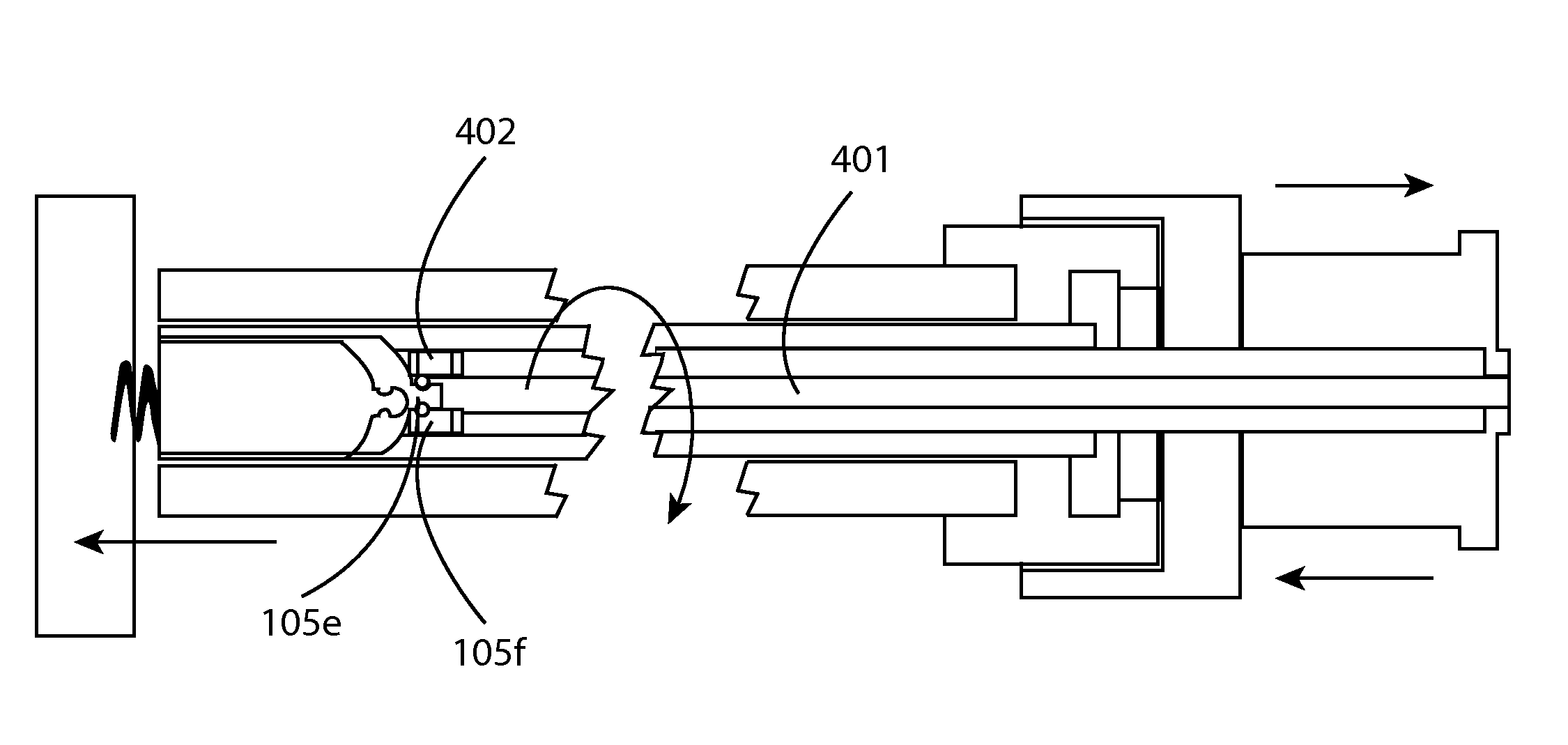
[0025]FIG. 4 shows a side view of the invention having an adapter that includes ball and ramp 105f at the distal end 402 coupled with at least one wire 401 within the adapter wherein the at least one wire may enable the adapter to rotate when the rotational force is applied to the at least one wire near the proximal end of the adapter. In one embodiment a helix or double helix may be utilized as the at least one wire 401 to provide the rotational force within the adapter. Any mechanism at the proximal side of the adapter may be utilized to impart the rotational force including manual or automated mechanisms for example. In one or more embodiments, the implantable device includes a corresponding rotational element 105e to enable the adapter to impart the rotational force to rotate the implantable device via the ball and ramp. In one or more embodiments, the ball and ramp may disengage the adapter from the implantable device when longitudinal force is applied in a direction away from ...


PUM


Abstract

A leadless implantable device delivery apparatus that enables testing of an implantation site before permanent implantation and enables secure attachment at the site while minimizing effects of the implantation procedure. Embodiments include a delivery sheath configured to accommodate a leadless implantable device, the leadless implantable device having an anchor that includes at least one projection configured to physically attach the anchor to tissue, such as heart tissue. In addition, embodiments include an adapter that resides within the delivery sheath and is configured to impart rotational force at the distal end of the adapter that is applied to the proximal end of the adapter to rotate the anchor associated with the implantable device.

Description

[0001]This application claims the benefit of U.S. Provisional Patent Application 61 / 730,058, filed on 27 Nov. 2012, the specification of which is hereby incorporated herein by reference.BACKGROUND OF THE INVENTION[0002]1. Field of the Invention[0003]At least one embodiment of the invention generally relates to an apparatus for implantation of medical devices and more particularly, but not by way of limitation, relates to a leadless implantable device delivery apparatus.[0004]2. Description of the Related Art[0005]Implantable medical devices may be implanted in patients in need of cardiac monitoring and if necessary, electrical stimulation. Leadless implantable devices, such as a leadless pacemaker for example have been developed to eliminate problems associated with electrode leads, which are prone to failure over time. In addition, explantation of electrode leads that have been implanted for long periods of time increases the risk of complications. Electrical energy is sensed via t...

Claims


Application Information

Patent Timeline
Patent Type & Authority Applications(United States)
IPC IPC(8): A61N1/375
CPCA61N1/3756A61B17/3468
Inventor WENZEL, MATTHIASAYTON, MICHAEL J.NORDSTROM, KARL
Owner BIOTRONIK SE & CO KG
Why Eureka
Try Eureka