Vehicle body rear structure

Active Publication Date: 2014-06-05
TOYOTA JIDOSHA KK
View PDF35 Cites 16 Cited by
  • Summary
  • Abstract
  • Description
  • Claims
  • Application Information

AI Technical Summary

Benefits of technology

[0023]According to the vehicle body rear structure, the upper end portion of the roof side outer is located on the vehicle bottom side compared to the upper end portion of the roof side inner and is not joined to the upper end portion of the roof side inner. Thus, when a load toward the top of the vehicle is transmitted from a suspension that supports a rear wheel to the suspension tower and the vehicle body undergoes torsional deformation and when the roof side inner undergoes torsional deformation which tends to displace the upper end portion thereof outward in a vehicle width direction, the torsional deformation of the roof side inner is prevented

Problems solved by technology

However, in such an upper back structure for a vehicle, when a load toward the top of the vehicle is transmitted from a suspension that supports a rear wheel to a suspension tower, the vehicle body undergoes torsional defo

Method used


Image

  • Vehicle body rear structure
  • Vehicle body rear structure
  • Vehicle body rear structure

Examples


Embodiment Construction

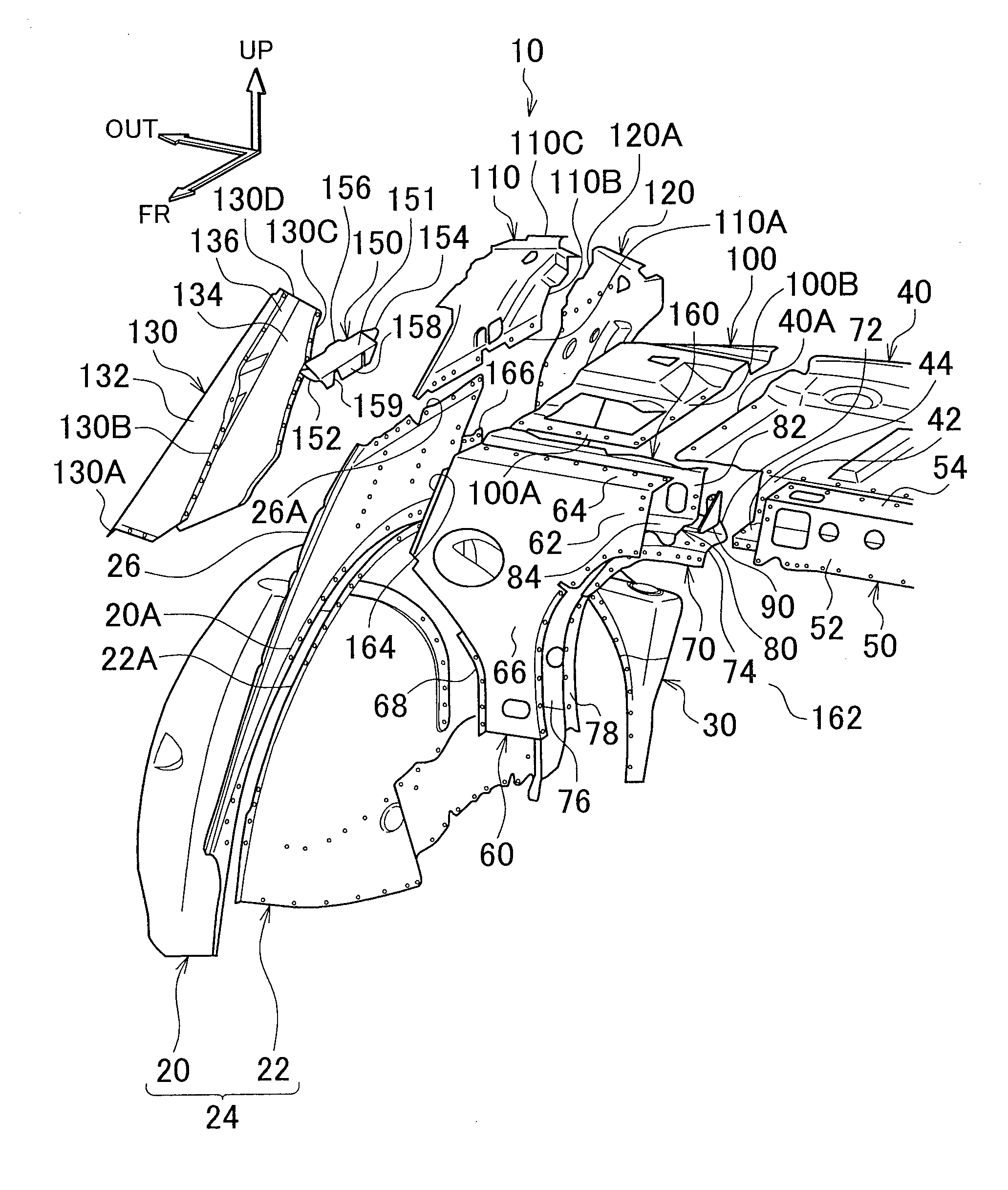
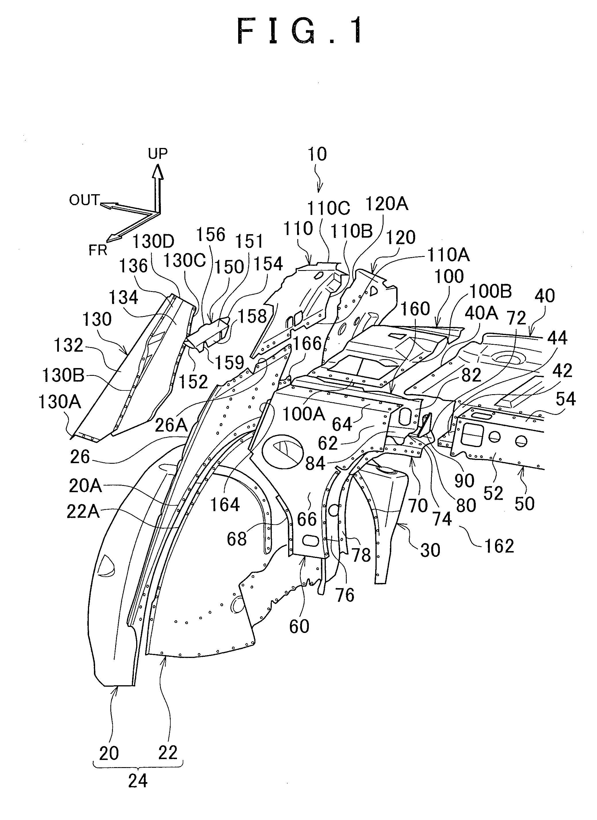
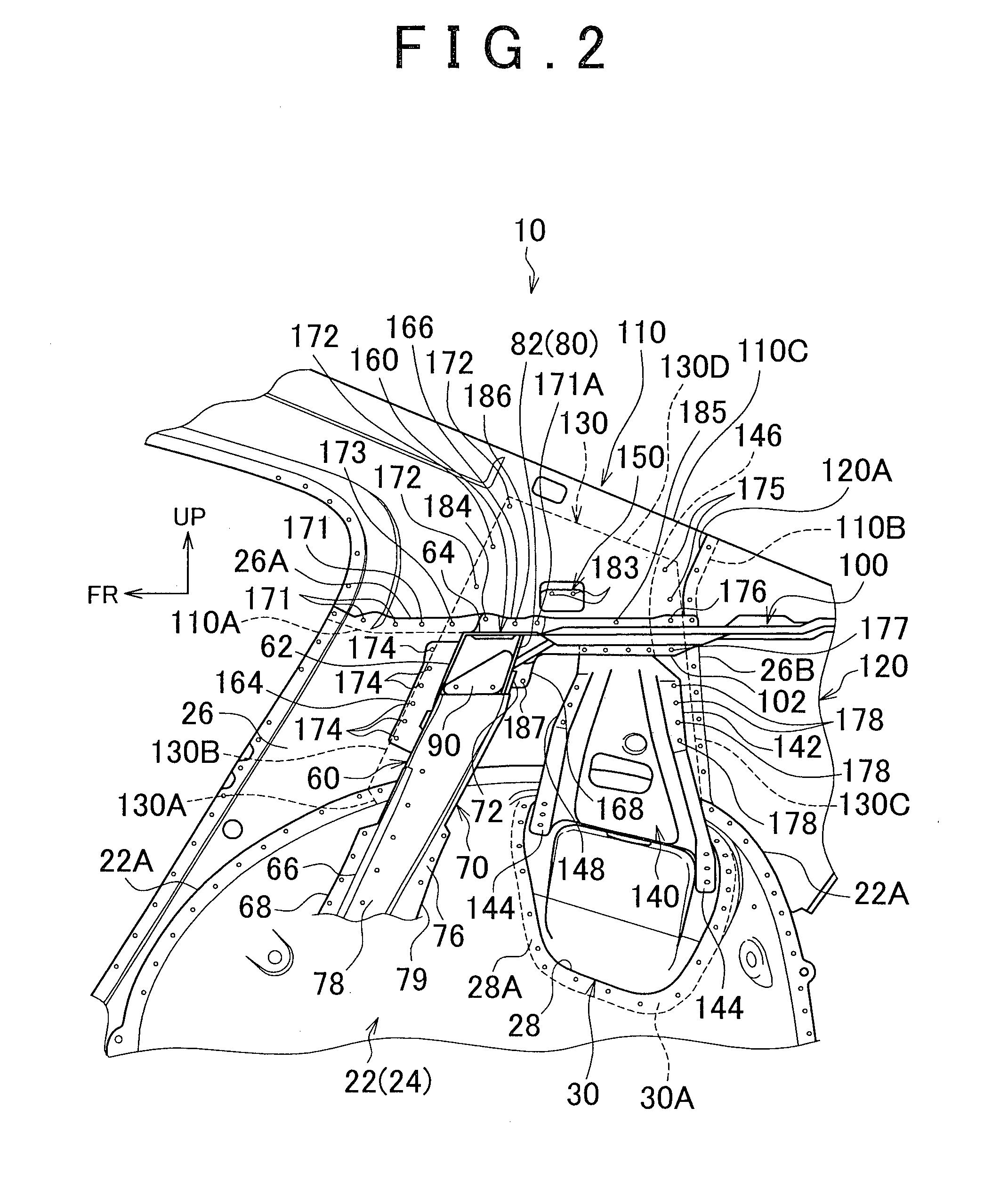
[0036]Description is hereinafter made of one embodiment of the present invention with reference to the drawings. The arrow UP, arrow FR and arrow OUT that are shown in the drawings indicate the upper side in a vehicle height direction, the front side in a vehicle length direction, and the outer side (right side) in a vehicle width direction, respectively.

[0037]As shown in FIG. 1, a vehicle body rear structure 10 according to one embodiment of the present invention includes a wheel house outer 20, a wheel house inner 22, a suspension tower plate 30, an upper back 40, an upper back outer 50, a strainer front 60, a strainer rear 70, a bracket package tray reinforcement 80, an upper back reinforcement 90; a bracket package tray 100, a roof side inner 110, a roof side inner rear 120, a roof side outer 130, a suspension tower gusset 140 (refer to FIG. 2), and a bulk 150.

[0038]The wheel house outer 20 and the wheel house inner 22 are located on one side in the rear of the vehicle and divid...


PUM


Abstract

A vehicle body rear structure includes an upper back cross-sectional portion which forms a skeleton that is elongated in a vehicle width direction, a bracket package tray which is located on a vehicle rear side of the upper back cross-sectional portion and joined to the upper back cross-sectional portion, a roof side inner which is located on a vehicle top side of a wheel house, a roof side outer which is located outside an extended portion and the roof side inner in a vehicle width direction and which has a front end portion which is joined to the upper back cross-sectional portion and a rear end portion which is joined to a bracket package tray, and a bulk which couples the roof side outer and the upper back cross-sectional portion.

Description

BACKGROUND OF THE INVENTION[0001]1. Field of the Invention[0002]The present invention relates to a vehicle body rear part structure.[0003]2. Description of Related Art[0004]An upper back structure for a vehicle which includes a pair of strainers, each of which has a lower end portion which is joined to a longitudinal end of a rear floor cross member and an upper end portion that is located on an upper edge of an opening that communicates the cabin with the trunk room, a pair of package tray brackets that are supported by the pair of strainers, and an upper back side panel that are joined to upper end portion of the package tray brackets is disclosed in Japanese Patent Application Publication No. 2003-312544 (JP 2003-312544 A), for example.[0005]In some of upper back structures for a vehicle of this type, the strainers and the upper back side panel are joined to a roof side outer that is located outside, the strainers and the upper back side panel in a vehicle width direction. Exampl...

Claims


Application Information

Patent Timeline
IPC IPC(8): B62D25/08
CPCB62D25/08B62D25/087B62D25/2027B62D25/2036
Inventor YANO, NORIMASA
Owner TOYOTA JIDOSHA KK
Why Eureka
Try Eureka