Fixing device for fixing toner on sheet by heating toner, and image forming apparatus including fixing device

a technology of fixing device and fixing roller, which is applied in the direction of electrographic process apparatus, instruments, optics, etc., can solve the problems of uneven heat generation in the circumferential direction of the fixing film, small power consumption amount, and heavy rotation load on the fixing roller, so as to reduce the rotation load reduce the deformation of the rotatable heating element, and improve the effect of electric power transmission

Active Publication Date: 2014-06-05
CANON KK
View PDF11 Cites 3 Cited by
  • Summary
  • Abstract
  • Description
  • Claims
  • Application Information

AI Technical Summary

Benefits of technology

[0008]A feature of the present invention is to reduce a rotation load of a rotatable heating element, to reduce deformation of the rotatable heating element, and to realize efficient electric power transmission from a primary coil to a secondary coil.

Problems solved by technology

This fixing device has merits of a short time period required from the beginning of power supply until a fixable state is reached, and a small power consumption amount.
However, since the fixing device of Japanese Patent Laid-Open No. 06-202513 supplies electric power to the heat generation layer using a brush electrode, it readily causes heat generation unevenness in a circumferential direction of the fixing film.
This is caused by a wear of the electrode due to a sliding contact and an oxide layer formed upon discharging.
However, in the fixing device of Japanese Patent Laid-Open No. 2002-123113, since a ferrite core included in a fixing roller rotates together with the fixing roller, a rotation load on the fixing roller becomes heavier.
Furthermore, when the fixing roller is made of a flexible film-like member, the ferrite core as a load causes deformation such as torsion in the film.
When such problem is to be solved by increasing the rigidity of the film, a heat capacity of the film is increased, resulting in demerits in terms of a time period from the beginning of power supply unit a fixable state is reached, and power consumption.

Method used


Image

  • Fixing device for fixing toner on sheet by heating toner, and image forming apparatus including fixing device
  • Fixing device for fixing toner on sheet by heating toner, and image forming apparatus including fixing device
  • Fixing device for fixing toner on sheet by heating toner, and image forming apparatus including fixing device

Examples


first embodiment

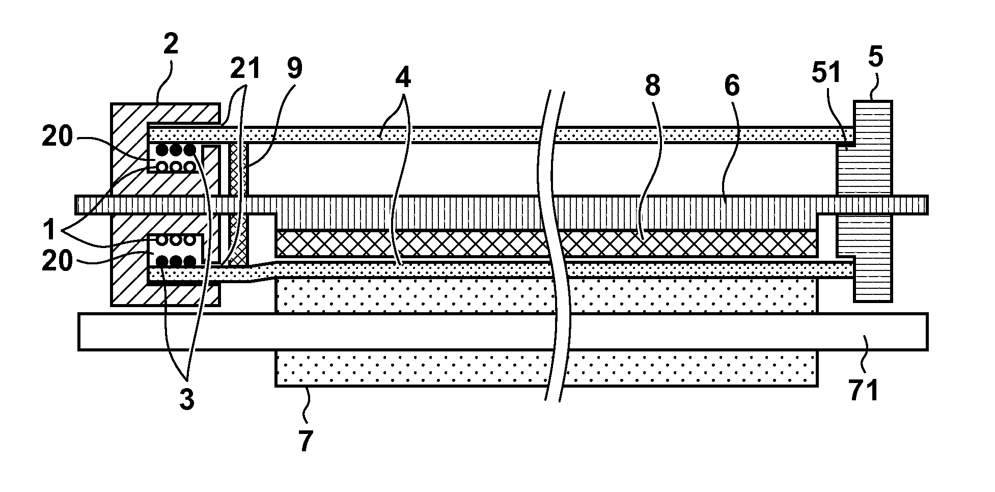
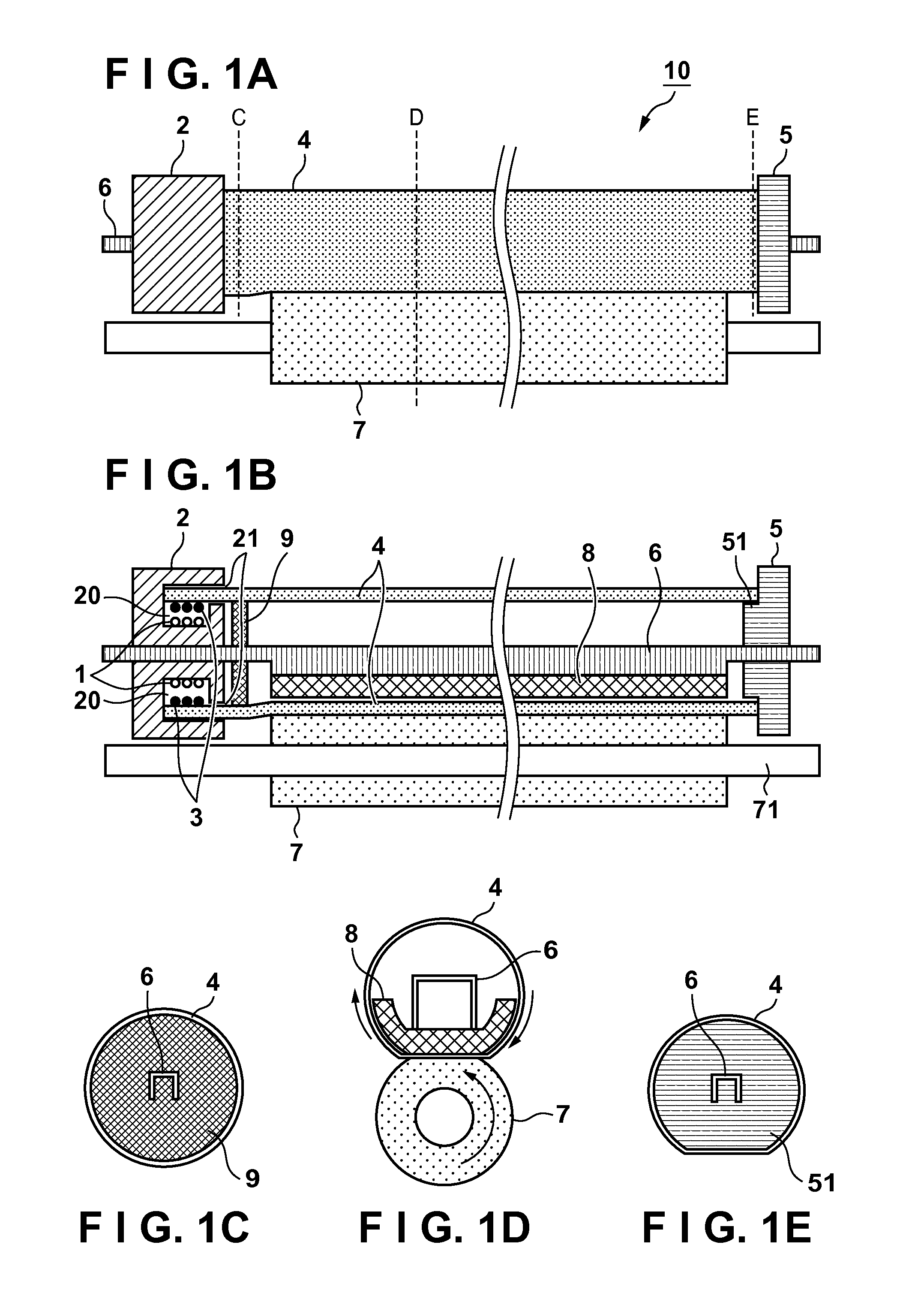
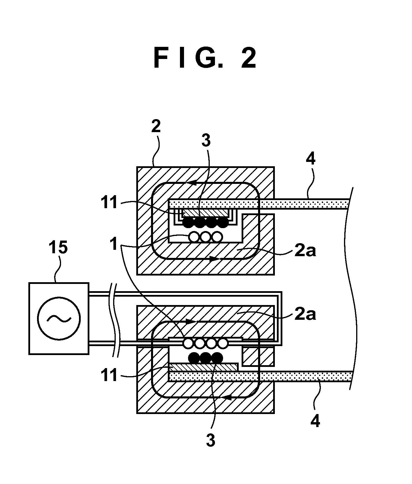
[0057]As described above, the secondary coil 3 is arranged in the end portion of the heating film 4, and the primary coil 1 and secondary coil 3 are arranged in the space 20 formed inside the core member 2. Since the core member 2 is designed to roughly surround the primary coil 1 and secondary coil 3, induction of a leaking magnetic flux can be suppressed to be low. Therefore, electric power can be efficiently transmitted from the primary coil 1 to the secondary coil 3. The core member 2 is fixedly arranged in the fixing device 10, and the rotating heating film 4 does not include the core member 2. For this reason, the rotation load on the heating film 4 can be reduced. That is, since the core member 2 does not impose any load on the heating film 4, the heating film 4 is nearly free from any deformation such as torsion.

[0058]The outer diameter of the primary coil 1 is smaller than the inner diameter of the secondary coil 3, and the primary coil 1 is arranged on the inner circumfer...

second embodiment

[0070]The shape of a core member 2 of the second embodiment will be described below with reference to FIGS. 9A, 9B, 9C, and 9D. FIG. 9A is a sectional view taken along a central axis direction (a direction parallel to a longitudinal direction of a heating film 4) of the core member 2. FIGS. 9B, 9C, and 9D are sectional views respectively taken along broken lines B, C, and D shown in FIG. 9A.

[0071]As shown in FIGS. 9B, 9C, and 9D, a sectional shape of each of a central portion 2a, left side surface 2b, outer circumferential surface 2c, and right side surface 2d of the core member 2 is circular in a portion and is flattened in the remaining portion.

[0072]That is, each of these sectional shape is quasi-circular (hog-backed or D shape). As described above, in order to form a fixing nip portion, a shape of a circumferential surface of a portion of the heating film 4 is flattened by shapes of a film guide 8 and fixing flange 5 during rotation. Thus, a sectional shape of a communicating po...


PUM


Abstract

A secondary coil is attached to an end portion of a heating film. A space is formed inside a core member. A primary coil, which generates a magnetic field that causes the secondary coil to generate a current by electromagnetic induction, is arranged inside the space together with the secondary coil.

Description

BACKGROUND OF THE INVENTION[0001]1. Field of the Invention[0002]The present invention relates to a fixing device for fixing toner on a sheet by heating the toner, and an image forming apparatus including the fixing device.[0003]2. Description of the Related Art[0004]An image forming apparatus of an electrophotography scheme or electrostatic recording scheme includes a fixing device used to fix an unfixed toner image formed on a sheet. According to Japanese Patent Laid-Open No. 06-202513, a fixing device, in which a heat generation layer is provided to a fixing film itself, and which supplies a current to this heat generation layer to directly heat the fixing film so as to heat and fix a toner image, has been proposed. This fixing device has merits of a short time period required from the beginning of power supply until a fixable state is reached, and a small power consumption amount. However, since the fixing device of Japanese Patent Laid-Open No. 06-202513 supplies electric power ...

Claims


Application Information

Patent Timeline
Patent Type & Authority Applications(United States)
IPC IPC(8): G03G15/20
CPCG03G15/5004G03G15/2053G03G21/1652G03G2215/2035
Inventor KIYAMA, KOTAHAYASHI, ISAO
Owner CANON KK
Why Eureka
Try Eureka