Clamping device for portable boring machine and portable air-drive-drilling machine with clamping device

Active Publication Date: 2014-06-05
SUGINO MACHINE
View PDF29 Cites 7 Cited by
  • Summary
  • Abstract
  • Description
  • Claims
  • Application Information

AI Technical Summary

Benefits of technology

The patent text describes a problem with the structure of a boring machine, where a cam is driven by a return spring and an air cylinder. This results in a complicated front end structure and a larger machine size, making it harder to operate and prone to chipping. The technical effect of the patent is to address this problem and improve the boring machine's operability and prevent chapping.

Problems solved by technology

Therefore, there is a problem that the structure around the front end of the boring machine is complicated and the boring machine is enlarged because of the air cylinder, so that operability of the boring machine turns worse, and chips easily clog the boring machine.
Furthermore, positions of the workpiece and a clamping device are fixed, so a position for fixing a mandrel cannot be adjusted.
Therefore, control is complicated because of the electric motor, and there is needed a dust-preventing processing for powder dust or mist.
Therefore, there is a problem that the structure around the front end of the boring machine is complicated and the boring machine is enlarged.
And, when the electrical control of the clamping mechanism is done, a control system is complicated in a case of adopting an air motor for driving the boring machine.
Therefore, there is a problem that operability of the boring machine turns worse and it is hard to control the operational timings.

Method used


Image

  • Clamping device for portable boring machine and portable air-drive-drilling machine with clamping device
  • Clamping device for portable boring machine and portable air-drive-drilling machine with clamping device
  • Clamping device for portable boring machine and portable air-drive-drilling machine with clamping device

Examples


Embodiment Construction

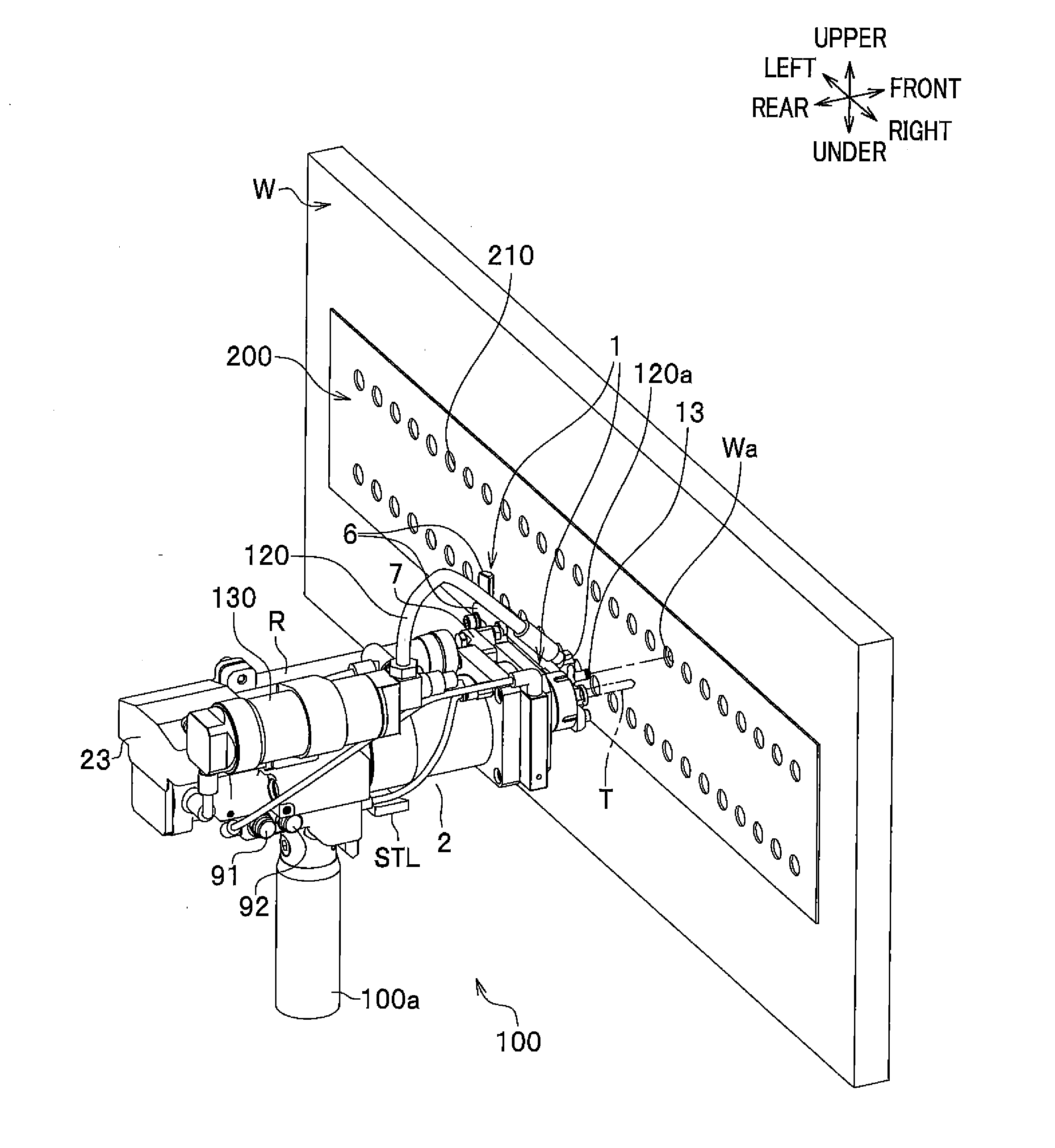
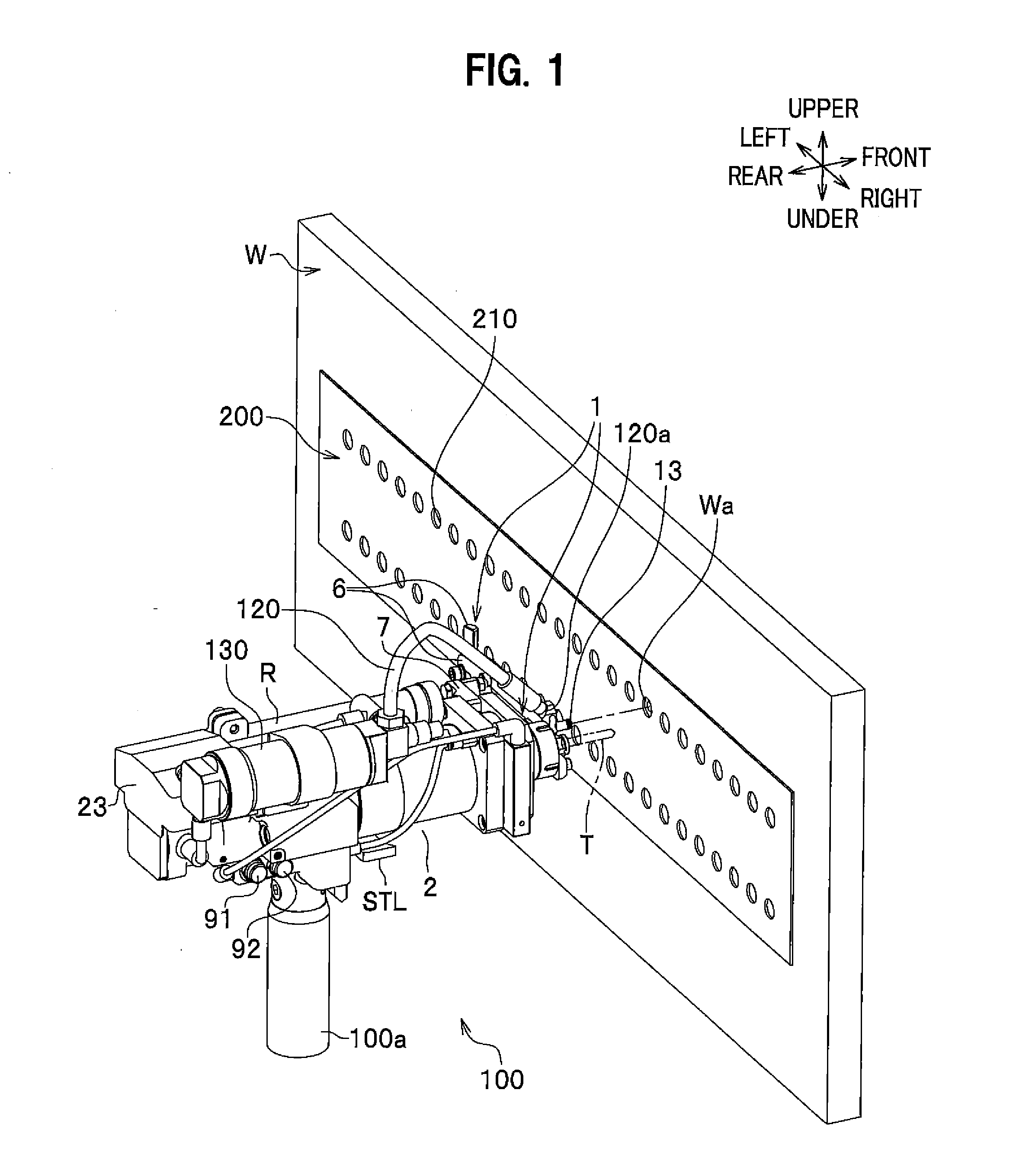
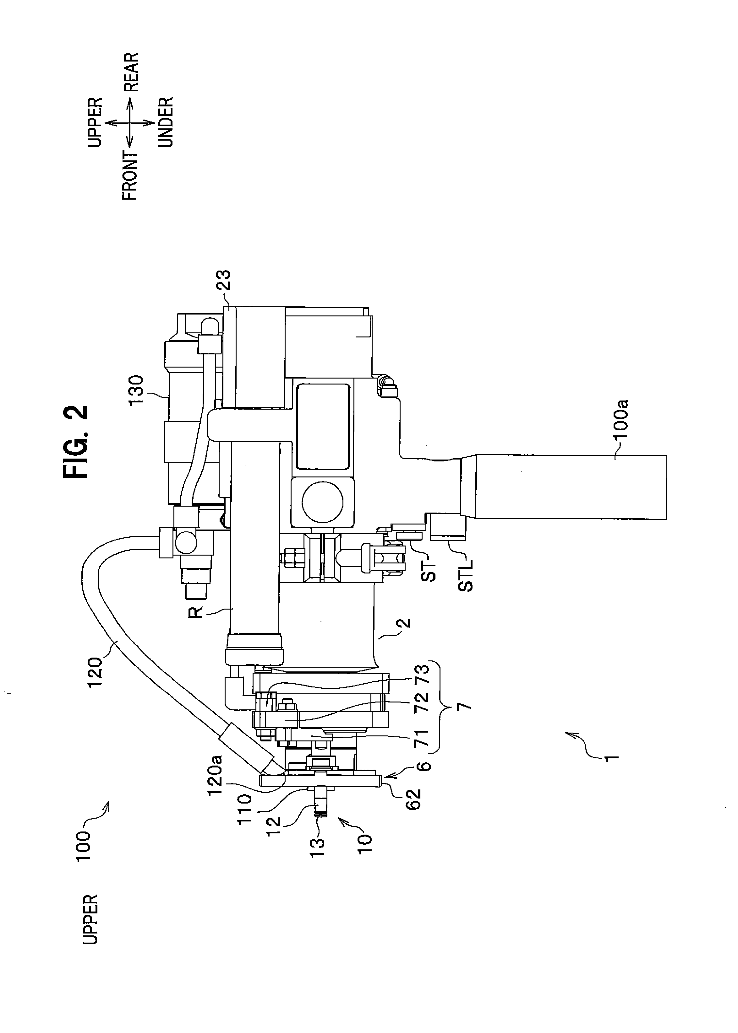
[0054]A clamping device 1 for a portable boring machine (a portable drilling machine driven by pressurized air 100) and the portable drilling machine driven by pressurized air 100 (hereinafter, drilling machine 100) of an embodiment according to the present invention will be explained with reference to the accompanying drawings in the following. A generic name for the clamping device 1 and the drilling machine 100 is “portable air-drive-drilling machine with a clamping device”.

[0055]The clamping device 1 is, for example, a device for clamping a boring machine and a workpiece to be bored by the boring machine. A case of use of the drilling machine 100 as the boring machine will be explained for an embodiment of the clamping device 1 according to the present invention in the following.

[0056]As shown in FIG. 1, the drilling machine 100 (boring machine) may be any boring unit to bore a workpiece W by rotating a boring tool. A drilling device having a boring tool like a drill T will be e...


PUM


Abstract

A clamping device is attached to a front part of a body of a boring machine for clamping the boring machine and a workpiece together. The clamping device comprises a fixed piston fixed on the front part of the body, a movable piston equipped over the front part of the body movably in the axial direction of a spindle of the boring machine, a first pressure chamber, a second pressure chamber, a pressurized fluid-supply device to supply pressurized air to the first pressure chamber and the second pressure chamber so that the movable cylinder is moved in the axial direction, a connecting mechanism an end portion of which is connected to the movable cylinder, and a clamping unit which is connected to the other end portion of the connecting mechanism, and is fixed to a certain position of the workpiece.

Description

CROSS REFERENCE TO RELATED APPLICATIONS[0001]This application claims the foreign priority benefit under Title 35, United States Code, 119 (a)-(d) of Japanese Patent Application No.2012-266722 which was filed on Dec. 5, 2012 in the Japan Patent Office, the disclosure of which is herein incorporated by reference in its entirety.BACKGROUND OF THE INVENTION[0002]1. Technical Field[0003]The present invention relates to a clamping device for a portable boring machine which is for boring a workpiece, and a portable air-drive-drilling machine with the clamping device. The clamping device is for clamping the portable boring machine and the workpiece together.[0004]2. Description of Background Art[0005]In a portable boring machine for boring a workpiece, the technique for boring a workpiece while clamping the portable boring machine and the worpiece together in the fixed state so that a position to be bored and posture between the machine and the workpiece are stable when the workpiece is bor...

Claims


Application Information

Patent Timeline
IPC IPC(8): B23B45/00B23B47/28
CPCB23B47/28B23B45/003B23B45/04B25F5/00B25H1/0021B23B31/20125B23B2247/04B23B2247/12Y10T408/557Y10T408/563B23B45/00B23B45/02B23Q3/06B23B2215/04
Inventor IHARA, MINORUUCHIUZO, HIDEKI
Owner SUGINO MACHINE
Why Eureka
Try Eureka