

Electronic-device cooling system
- Summary
- Abstract
- Description
- Claims
- Application Information
AI Technical Summary
Benefits of technology
Problems solved by technology
Method used
Image

Examples
Embodiment Construction
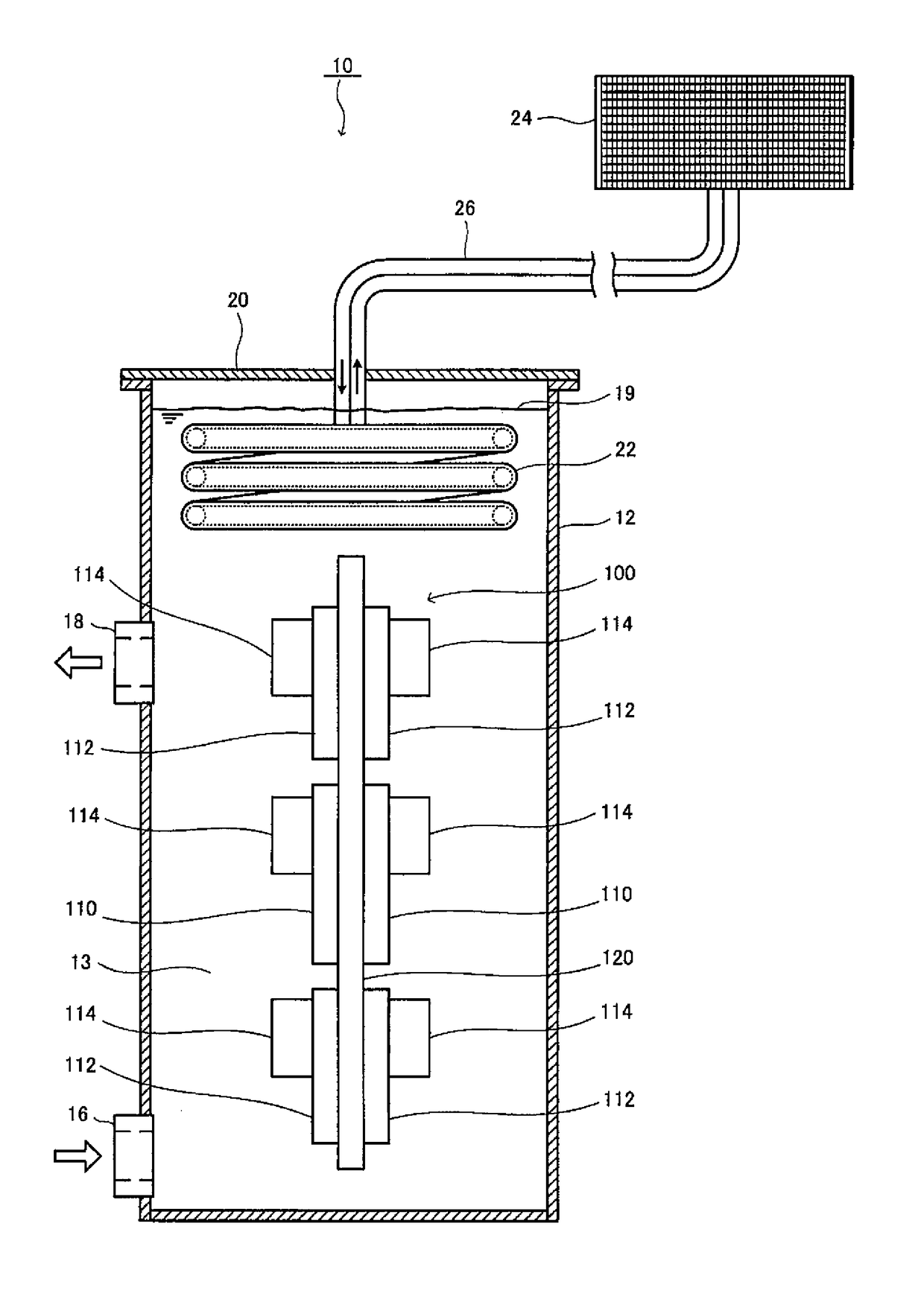
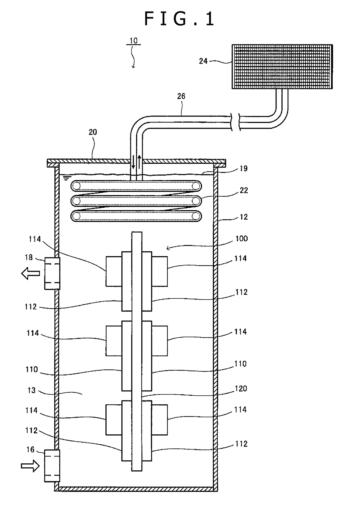
[0030]Hereinafter, preferred embodiments of a cooling system according to the present invention will be described in detail with reference to the drawings. In the description of the present embodiments, first of all, with reference to FIG. 1 to FIG. 3, there will be described as one preferred embodiment a structure of an important portion of a cooling system in which an electronic device of the configuration arranging three processor boards, each mounting a processor comprising a CPU or a GPU, on one surface of a board is housed in a cooling tank to be cooled. Then, with reference to FIG. 4, one unit only of the electronic device of the same configuration is shown schematically, and description will be made regarding the whole structure of the cooling system for cooling the electronic device with the same stored in the cooling tank. Subsequently, as the other preferred embodiment, with reference to FIG. 5 to FIG. 7, the structure of a high-density cooling system will be described wh...
PUM
 Abstract
Description
Claims
Application Information