
Flexible conductor (BRAID) bonded to low material cost plug on jaw

a flexible conductor and plug technology, applied in the field of circuit breakers, can solve the problems of reducing the useful affecting the mechanical performance affecting the service life of the circuit breaker, so as to reduce the negative impact of the mechanical, and improve the contact point. the effect of low resistan

Inactive Publication Date: 2014-06-12
SCHNEIDER ELECTRIC USA INC
View PDF5 Cites 5 Cited by
  • Summary
  • Abstract
  • Description
  • Claims
  • Application Information

AI Technical Summary

Benefits of technology

The invention is about a new circuit breaker design that prevents damage to the contacts during switching and reduces the likelihood of arcing. The design uses a floating contact assembly that automatically adjusts to the position of the moveable contact when engaged. This helps to keep the contacts connected at a single point of contact, minimizing damage caused by arcing. The flexible conductor of the assembly helps to maintain direct contact with an external electrical component, even when the jaw member of the circuit breaker is subject to mechanical forces. This design saves on precious metal and improves the connection between the circuit breaker and external electrical components.

Problems solved by technology

Because the moveable and stationary contacts are initially brought into physical contact with one another when the circuit breaker is turned ON, arcing can occur therebetween which, over time, can damage the contacts and can reduce the useful life of the circuit breaker.
Similar arcing and damage can occur when the moveable and stationary contacts are disconnected in response to the circuit breaker turning OFF.
Additionally, due to the nature of imperfections of the contacts, especially when damaged from arcing, for example, a planar engagement between the exposed surfaces of the contacts is not always established.
As such, due to the mechanical-plug-on type connection, movement of components, such as, for example, vibration of a housing of the electrical enclosure, can negatively impact the mechanical and electrical connection between the stationary contact and the moveable contact.

Method used


Image

  • Flexible conductor (BRAID) bonded to low material cost plug on jaw
  • Flexible conductor (BRAID) bonded to low material cost plug on jaw
  • Flexible conductor (BRAID) bonded to low material cost plug on jaw

Examples


Embodiment Construction

[0031]Although the present disclosure will be described in connection with certain preferred implementations of the disclose concepts, it will be understood that the present disclosure is not limited to those particular implementations. On the contrary, the present disclosure is intended to include all alternatives, modifications and equivalent arrangements as may be included within the spirit and scope of the present disclosure as defined by the appended claims.

[0032]Words of degree, such as “about”, “substantially”, and the like are used herein in the sense of “at, or nearly at, when given the manufacturing, design, and material tolerances inherent in the stated circumstances” and are used to prevent the unscrupulous infringer from unfairly taking advantage of the present disclosure where exact or absolute figures and operational or structural relationships are stated as an aid to understanding the present disclosure.

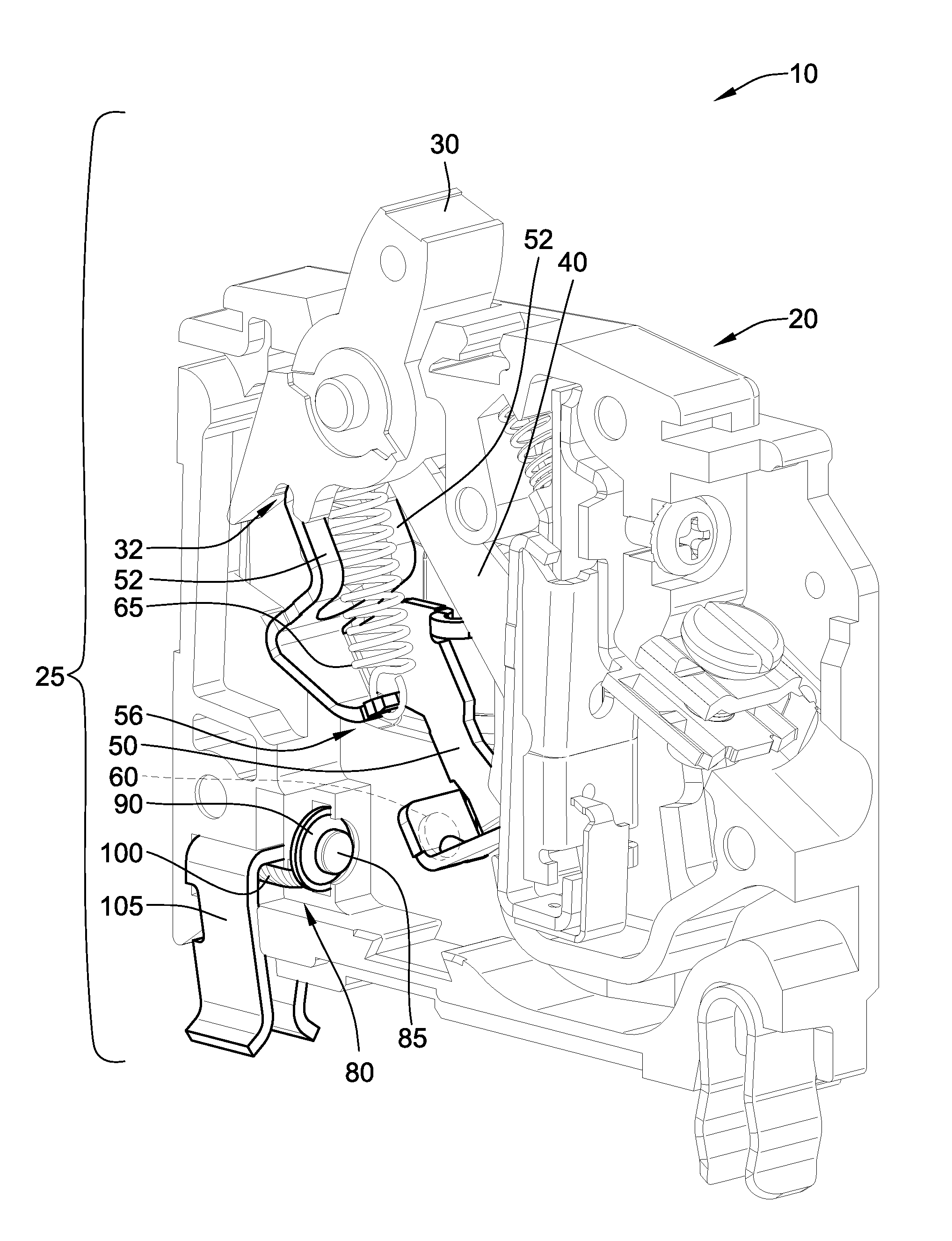
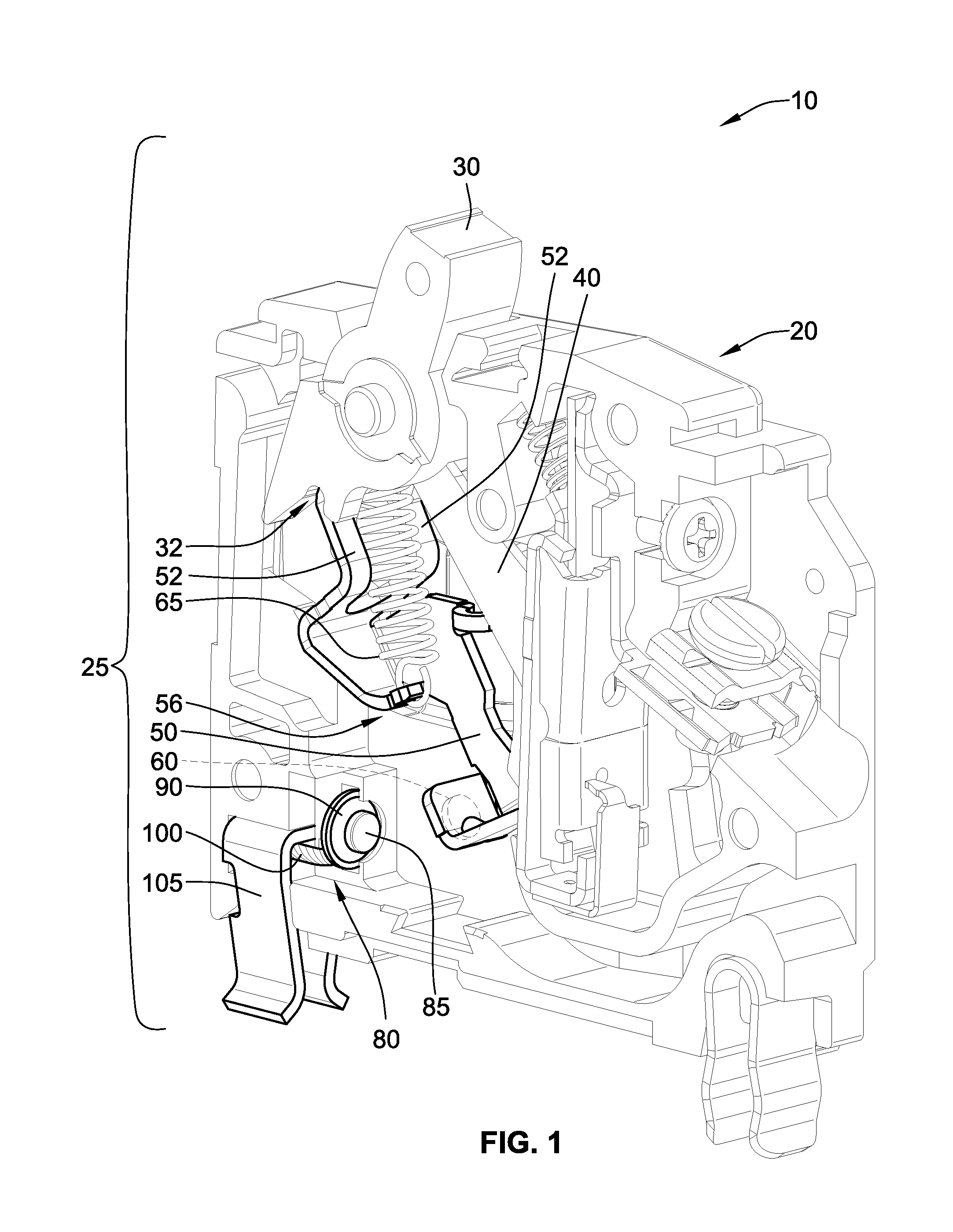
[0033]Referring to FIG. 1, a circuit breaker 10 with a cover rem...


PUM


Abstract

A substitute for the traditional single piece fixed contact / jaw member on a line-side of a miniature circuit breaker includes a line-side jaw member (e.g., a clip), a flexible conductor (e.g., braided wire), and a line-side contact. The line-side jaw member uses any springy metal or plastic for the clip function and inside the jaw member is the flexible conductor acting as a conductor (e.g., electrically connecting the circuit breaker to a busbar). The flexible conductor leads to the line-side contact. Such an arrangement can save on conductive metal in a circuit breaker. Additionally, the flexible conductor may provide better and more contact points for conduction.

Description

FIELD OF THE INVENTION[0001]This invention is directed generally to a circuit breaker, and, more particularly, to a circuit breaker having a flexible conductor bonded to a plug on jaw.BACKGROUND OF THE INVENTION[0002]Circuit breakers provide automatic and manual current interruption to a circuit. The act of turning ON a circuit breaker and closing an electrical circuit typically involves a mechanical movement of a series of mechanical parts that results in a moveable contact making an electrical connection with a stationary (e.g., fixed) and / or line-side contact. Because the moveable and stationary contacts are initially brought into physical contact with one another when the circuit breaker is turned ON, arcing can occur therebetween which, over time, can damage the contacts and can reduce the useful life of the circuit breaker. Similar arcing and damage can occur when the moveable and stationary contacts are disconnected in response to the circuit breaker turning OFF. Additionally...

Claims


Application Information

Patent Timeline
Patent Type & Authority Applications(United States)
IPC IPC(8): H01H1/58
CPCH01H1/58H01H1/18H01H1/50H01H1/5822H01H73/04H01H2001/5827
Inventor MITTELSTADT, CHAD R.
Owner SCHNEIDER ELECTRIC USA INC
Learn More