Gas generator and turbojet fitted with such a generator for starting

a gas generator and turbojet technology, applied in the field of pressurized gas generators, can solve the problems of increasing the outside diameter of the turbojet and the increase in the diameter can be completely unacceptable, and achieve the effect of reducing the impact of the gas generator

Inactive Publication Date: 2010-02-09
ARIANEGRP SAS
View PDF5 Cites 0 Cited by
  • Summary
  • Abstract
  • Description
  • Claims
  • Application Information

AI Technical Summary

Benefits of technology

[0006]An object of the present invention is to provide a gas generator of a design that enables its components to be well integrated in the structure of the vehicle with which it is used in order to eliminate or reduce the impact of the gas generator on the overall size of said vehicle.
[0008]In addition, the pyrotechnic charge is constituted by a plurality of unit charge elements disposed one behind another within the casing. The use of unit elements disposed in ordered manner within the casing makes it possible firstly to facilitate loading the generator in spite of the annular shape of its casing, and secondly to obtain a charge having physical characteristics that are constant and ensure good reproducibility of pyrotechnic operation, as is not the case with a bulk charge, for example.
[0014]This object is achieved by fitting the turbojet with the above-described gas generator. In accordance with the invention, the gas generator comprises an annular or semi-annular casing housing a pyrotechnic charge which, during combustion, produces gas that enables the compressor or the turbine of the turbojet to be set into rotation. Thus, because of its ring or part-ring structure, the casing is close to the outside shape of the engine and enables the pyrotechnic charge to be distributed around the engine, thereby eliminating or at least minimizing any increase in the caliber of the vehicle.
[0017]When the gas generator is placed in the vicinity of the compressor, the compressed air feed torous already present on the turbojet and used for starting during reception testing on the factory workbench can advantageously be used to form the casing for storing the charge. This enables the design of the starter device to be even more integrated.

Problems solved by technology

Such a system is particularly penalizing in terms of missile caliber since it leads inevitably to an increase in the outside diameter of the turbojet.
Such an increase in diameter can be completely unacceptable, particularly when the size of the missile is limited by the amount of room available in launch devices such as the torpedo tubes of a submarine.

Method used


Image

  • Gas generator and turbojet fitted with such a generator for starting
  • Gas generator and turbojet fitted with such a generator for starting
  • Gas generator and turbojet fitted with such a generator for starting

Examples


Embodiment Construction

[0025]The gas generator of the present invention is described in particular as a device for starting a turbojet. Nevertheless, the invention applies more generally to any machine needing to use gas generators and for which minimizing the size of such a device is of special importance. Thus, the person skilled in the art will have no difficulty in devising other applications for the invention.

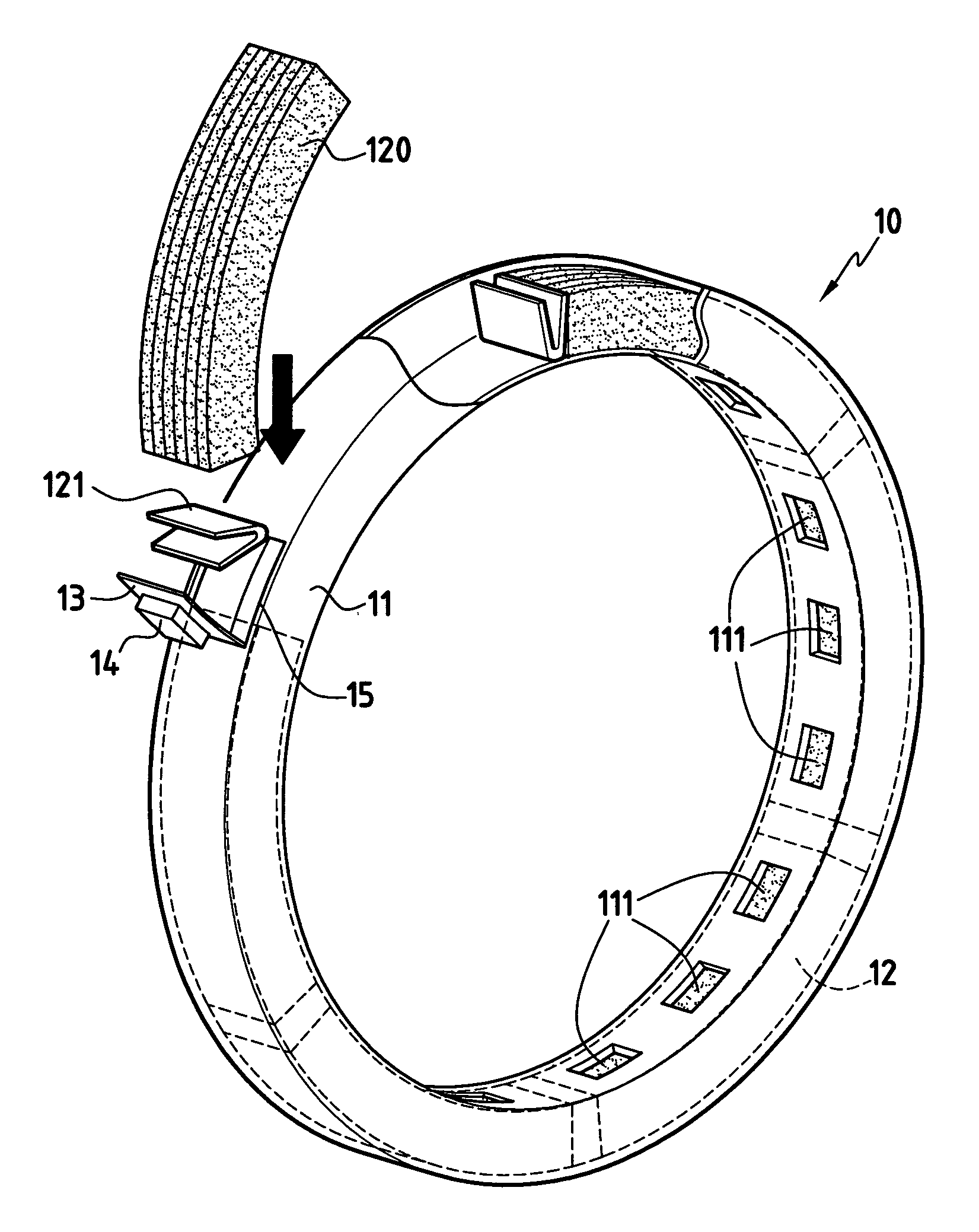
[0026]FIG. 1 shows an embodiment of a gas generator in accordance with the invention. The gas generator 10 comprises an annular casing 11 forming a chamber for a pyrotechnic charge 12 made up of a plurality of unit charge segments 120. Each segment 120 is constituted, for example, by a block of solid propellant of curved shape corresponding to the curvature of the casing. The segments 120 can be shaped by molding or by bending. The segments present outside dimensions that are perceptibly smaller than those of the housing formed by the casing 11 so as to leave passages between the segments and th...


PUM


Abstract

A gas generator comprises a casing forming a ring or a ring portion and housing a pyrotechnic charge, the casing including at least one vent for ejecting the gas produced during combustion of the charge. Because of its ring design, the gas generator is easy to integrate in the structure of a rotary machine. In particular, it can constitute a starter device for a turbojet.

Description

[0001]This application claims priority to a French application No. 03 13639 filed Nov. 21, 2003.BACKGROUND OF THE INVENTION[0002]The present invention relates to the pressurized gas generators that are used for driving rotary machines such as turbojets.[0003]The field of application of the invention is more particularly, but not exclusively, that of cruise missiles provided with turbojets, and for which overall diametral size is limited.[0004]A cruise missile uses a turbojet for propulsion while in a stabilized stage. For missiles that are launched from an airplane, the turbojet can start while windmilling because of the speed and the altitude from which it is released. For versions that are launched from a ship or a submarine, a gas generator is needed to ensure that the turbojet is set quickly into rotation. More precisely, the flow of gas coming from the generator is used to put the turbine of the turbojet into action.[0005]The gas generators presently used for starting the turbo...

Claims


Application Information

Patent Timeline
Patent Type & Authority Patents(United States)
IPC IPC(8): F02C3/26F01D19/00F02C7/272F42B3/04
CPCF01D19/00F02C7/272F42B3/04Y02T50/672Y02T50/60
Inventor SOULIE, LAURENTFISCHER, ROGER
Owner ARIANEGRP SAS
Why Eureka
Try Eureka