Air inlet combining a filter and a bypass device for use with a turbine engine

Active Publication Date: 2014-06-12
AIRBUS HELICOPTERS DEUT GMBH
View PDF11 Cites 15 Cited by
  • Summary
  • Abstract
  • Description
  • Claims
  • Application Information

AI Technical Summary

Benefits of technology

[0021]An object of the present invention is to provide an alternative air inlet solution tha

Problems solved by technology

As a result, the engine loses a larg

Method used


Image

  • Air inlet combining a filter and a bypass device for use with a turbine engine
  • Air inlet combining a filter and a bypass device for use with a turbine engine
  • Air inlet combining a filter and a bypass device for use with a turbine engine

Examples


Example

[0043]Elements present in more than one of the figures are given the same references in each of them.

[0044]FIG. 1 shows a rotary wing aircraft 50 having a fuselage 51 and an air inlet 10 of the invention, which air inlet includes in particular a filter system with a filter 3 and a bypass device 4. FIGS. 2 to 5 show this air inlet 10 in greater detail, the bypass device 4 being shown inactive in FIGS. 2 and 3 and being shown active in FIGS. 4 and 5.

DETAILED DESCRIPTION OF THE INVENTION

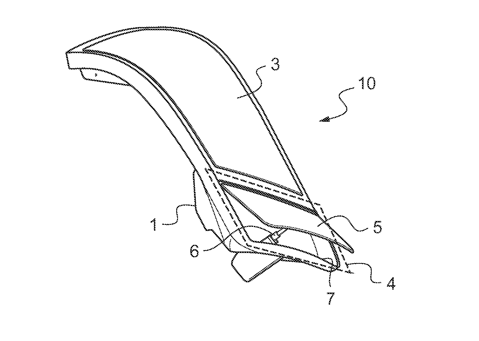
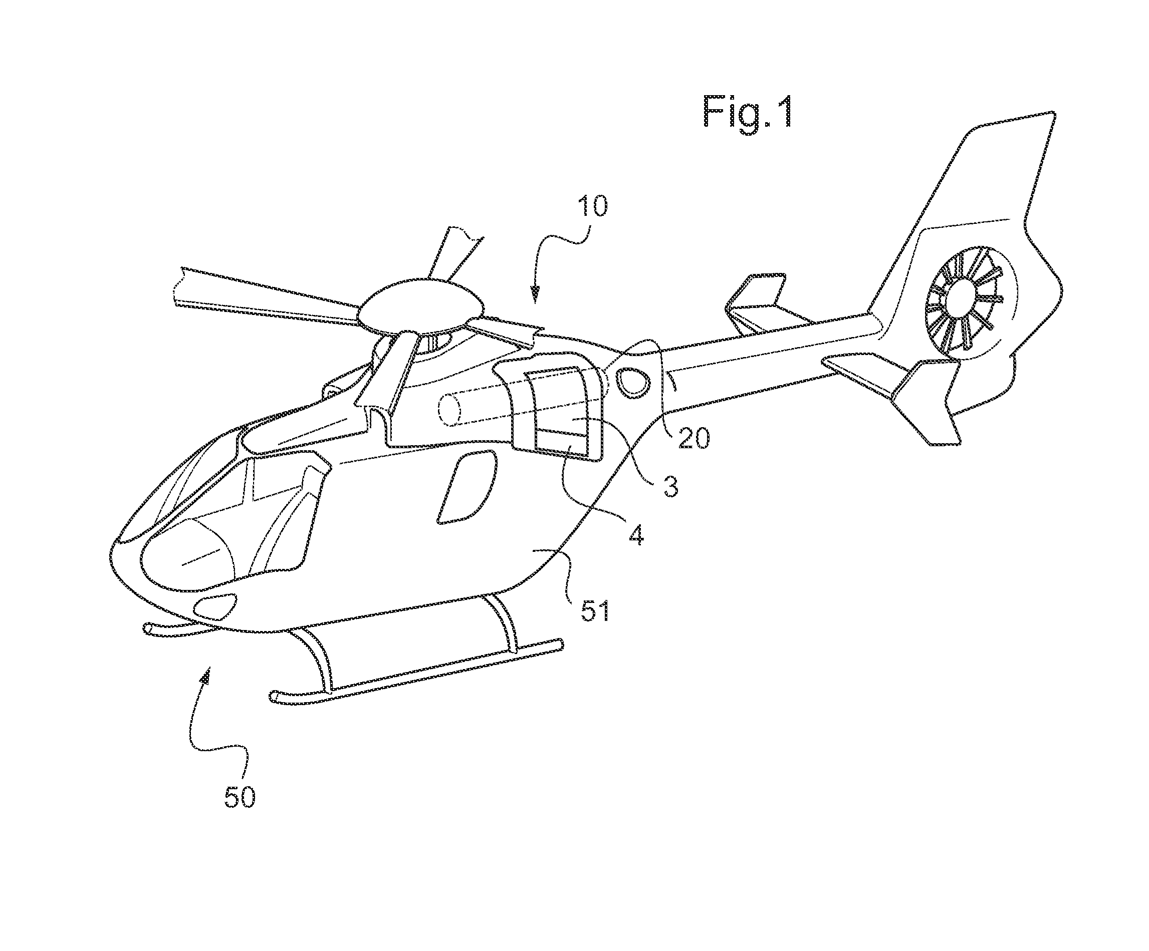
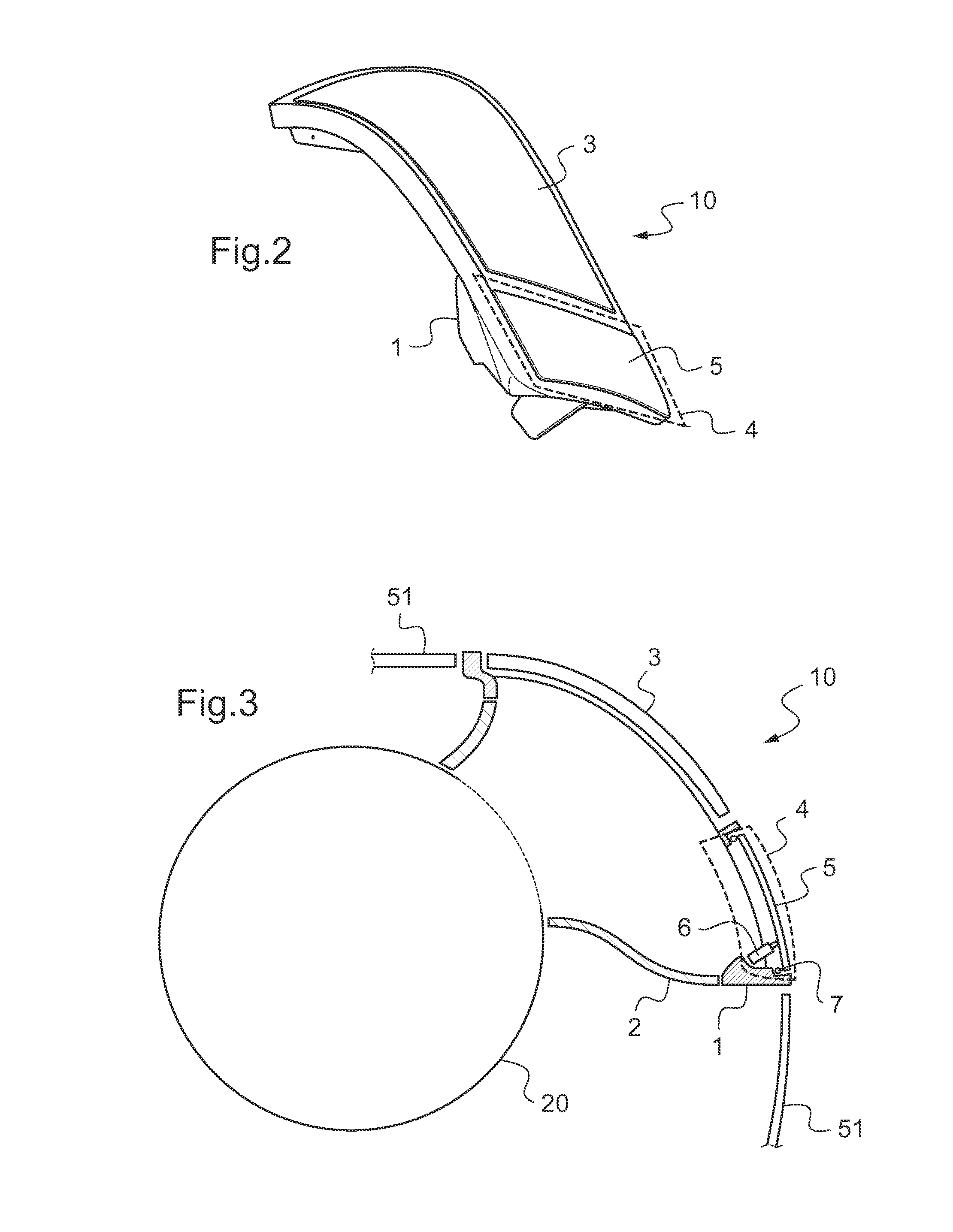
[0045]The air inlet 10 is situated in a flank of the fuselage 51 of the aircraft 50 and it is said to be “lateral” or “radial”. It is connected to an engine 20 of the aircraft 50 that it feeds with outside air. The aircraft 50 may have at least one other engine fed by another air inlet, e.g. an inlet situated in the other flank of the fuselage 51 of the aircraft 50. Furthermore, the air inlet 10 may also be situated in the top of the fuselage 51.

[0046]The air inlet 10 thus serves to feed outside air to ...


PUM


Abstract

An air inlet (10) for an engine (20) of an aircraft (50), the air inlet (10) having a duct (2) feeding outside air to said engine (20) together with a filter system combining at least one filter (3) and at least one bypass device (4). Said filter (3) and said bypass device (4) are fastened on a common support (1) situated at one end of said duct (2) and on a flank of a fuselage (51) of said aircraft (50). Said bypass device (4) comprises a cover (5) and an actuator (6) controlling opening of said cover (5). Thus, when said filter (3) no longer allows outside air to pass therethrough, said cover (5) is opened, and outside air passes via the bypass device (4) in order to feed said engine (20) with outside air.

Description

CROSS REFERENCE TO RELATED APPLICATION[0001]This application claims priority to European patent application No. 12 400053.0 filed Dec. 11, 2012, the disclosure of which is incorporated in its entirety by reference herein.BACKGROUND OF THE INVENTION[0002](1) Field of the Invention[0003]The present invention relates to an air inlet for an engine and more particularly for a turbine engine of a rotary wing aircraft. This air inlet is provided with a filter system combining at least one barrier filter with at least one bypass device. The technical field of the invention is thus the field of turbine engine air inlets, and more particularly the field of filter systems for such air inlets.[0004](2) Description of Related Art[0005]In order to feed each engine of an aircraft with outside air and thus enable the engine(s) to operate, the aircraft has at least one air inlet, each air inlet being provided with a filter system and with a duct connecting the engine(s) to the outside air.[0006]Furt...

Claims


Application Information

Patent Timeline
IPC IPC(8): B64D33/02
CPCB64D33/02B64C27/04B64D2033/0246B64D2033/0293
Inventor BRAEUTIGAM, RALF
Owner AIRBUS HELICOPTERS DEUT GMBH
Why Eureka
Try Eureka