Stabilization structure including sacrificial release layer and staging cavity

a stabilization structure and release layer technology, applied in the field of micro devices, can solve problems such as integration and packaging problems

Active Publication Date: 2014-06-12
APPLE INC
View PDF11 Cites 142 Cited by
  • Summary
  • Abstract
  • Description
  • Claims
  • Application Information

AI Technical Summary

Problems solved by technology

Integration and packaging issues are one of the main obstacles for the commercialization of micro devices such as radio frequency (RF) microelectromechanical systems (MEMS) microswitches, light-emitting diode (LED) display systems, and MEMS or quartz-based oscillators.

Method used


Image

  • Stabilization structure including sacrificial release layer and staging cavity
  • Stabilization structure including sacrificial release layer and staging cavity
  • Stabilization structure including sacrificial release layer and staging cavity

Examples


Embodiment Construction

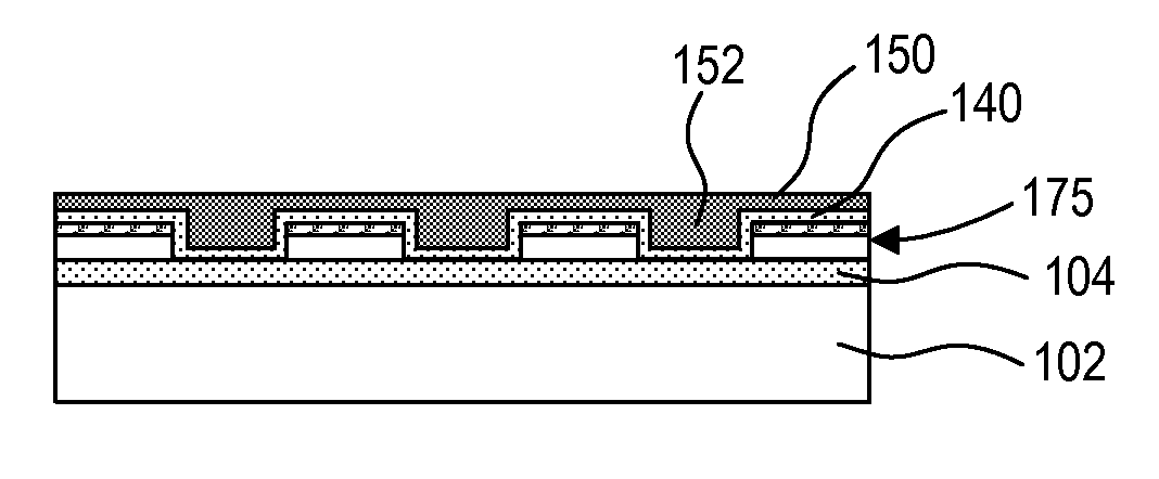
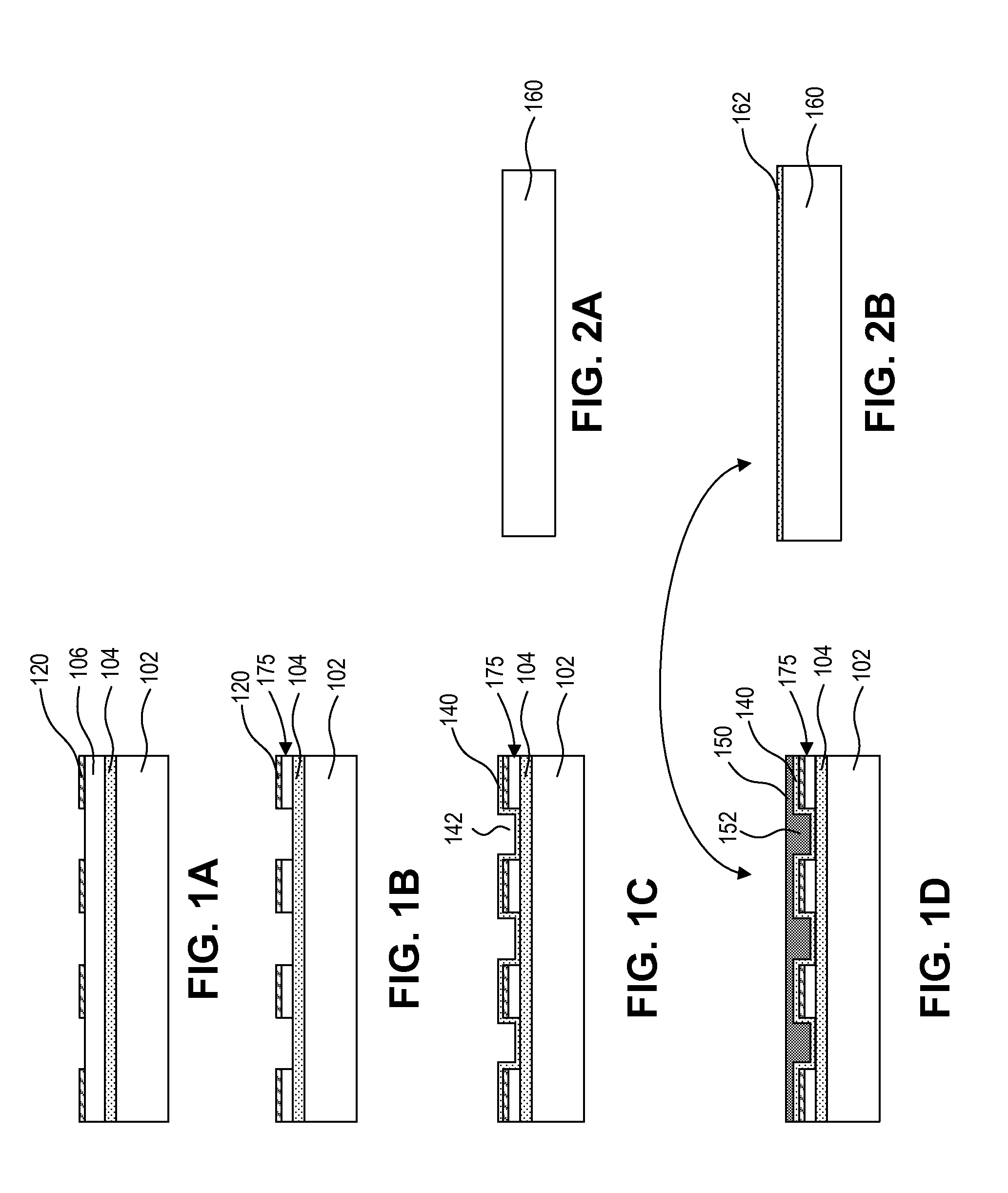
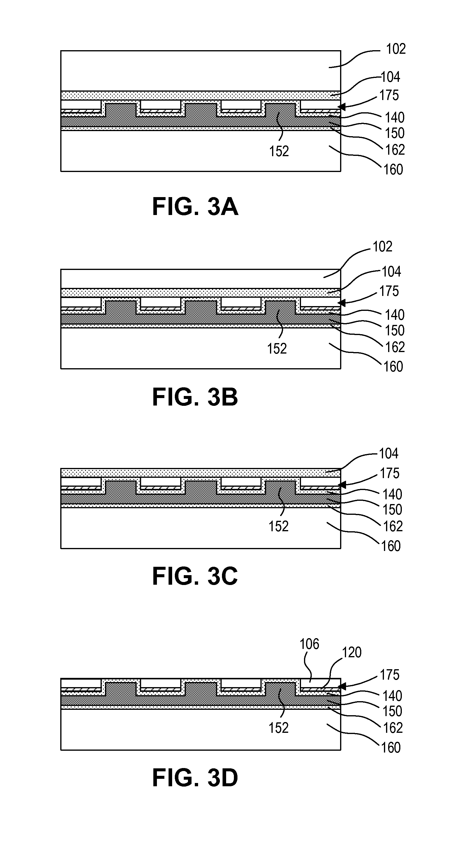
[0023]Embodiments of the present invention describe a method and structure for stabilizing an array of micro devices such as micro light emitting diode (LED) devices and micro chips on a carrier substrate so that they are poised for pick up and transfer to a receiving substrate. For example, the receiving substrate may be, but is not limited to, a display substrate, a lighting substrate, a substrate with functional devices such as transistors or integrated circuits (ICs), or a substrate with metal redistribution lines. While embodiments some of the present invention are described with specific regard to micro LED devices comprising p-n diodes, it is to be appreciated that embodiments of the invention are not so limited and that certain embodiments may also be applicable to other micro semiconductor devices which are designed in such a way so as to perform in a controlled fashion a predetermined electronic function (e.g. diode, transistor, integrated circuit) or photonic function (LE...


PUM


Abstract

A method and structure for stabilizing an array of micro devices is disclosed. The array of micro devices is held within an array of staging cavities on a carrier substrate. Each micro device is laterally surrounded by sidewalls of a corresponding staging cavity.

Description

RELATED APPLICATIONS[0001]This application claims the benefit of priority from U.S. Provisional Patent Application Ser. No. 61 / 735,958 filed on Dec. 11, 2012.BACKGROUND[0002]1. Field[0003]The present invention relates to micro devices. More particularly embodiments of the present invention relate to the stabilization of micro devices on a carrier substrate.[0004]2. Background Information[0005]Integration and packaging issues are one of the main obstacles for the commercialization of micro devices such as radio frequency (RF) microelectromechanical systems (MEMS) microswitches, light-emitting diode (LED) display systems, and MEMS or quartz-based oscillators.[0006]Traditional technologies for transferring of devices include transfer by wafer bonding from a transfer wafer to a receiving wafer. One such implementation is “direct printing” involving one bonding step of an array of devices from a transfer wafer to a receiving wafer, followed by removal of the transfer wafer. Another such ...

Claims


Application Information

Patent Timeline
Patent Type & Authority Applications(United States)
IPC IPC(8): H01L33/08H01L33/48
CPCH01L33/48H01L33/08H01L25/0753H01L27/153H01L2224/16225H01L2924/1461B81C99/002H01L24/80H01L2924/12042H01L2924/12041H01L24/75H01L24/81H01L24/83H01L24/95H01L2224/7598H01L2224/97H01L21/6835H01L2221/68318H01L2221/68368H01L2221/68381H01L2224/95001H01L33/0093H01L2224/95136H01L2924/00H01L2224/83H01L2224/81H01L27/156H01L21/56
Inventor HU, HSIN-HUABIBL, ANDREAS
Owner APPLE INC
Why Eureka
Try Eureka