Solar sunmill generator bulb

Active Publication Date: 2014-06-12
NUSPECIES GLOBAL MACHINES
View PDF7 Cites 9 Cited by
  • Summary
  • Abstract
  • Description
  • Claims
  • Application Information

AI Technical Summary

Benefits of technology

[0007]A second aspect of the present invention provides a solar generator having a bulb encasement configured and disposed to maintain a partial vacuum therewithin, the bulb encasement having a magnet, and a needle extending from a top side to a bottom side of a coil

Problems solved by technology

This ultimately causes the pr

Method used


Image

  • Solar sunmill generator bulb
  • Solar sunmill generator bulb
  • Solar sunmill generator bulb

Examples


Embodiment Construction

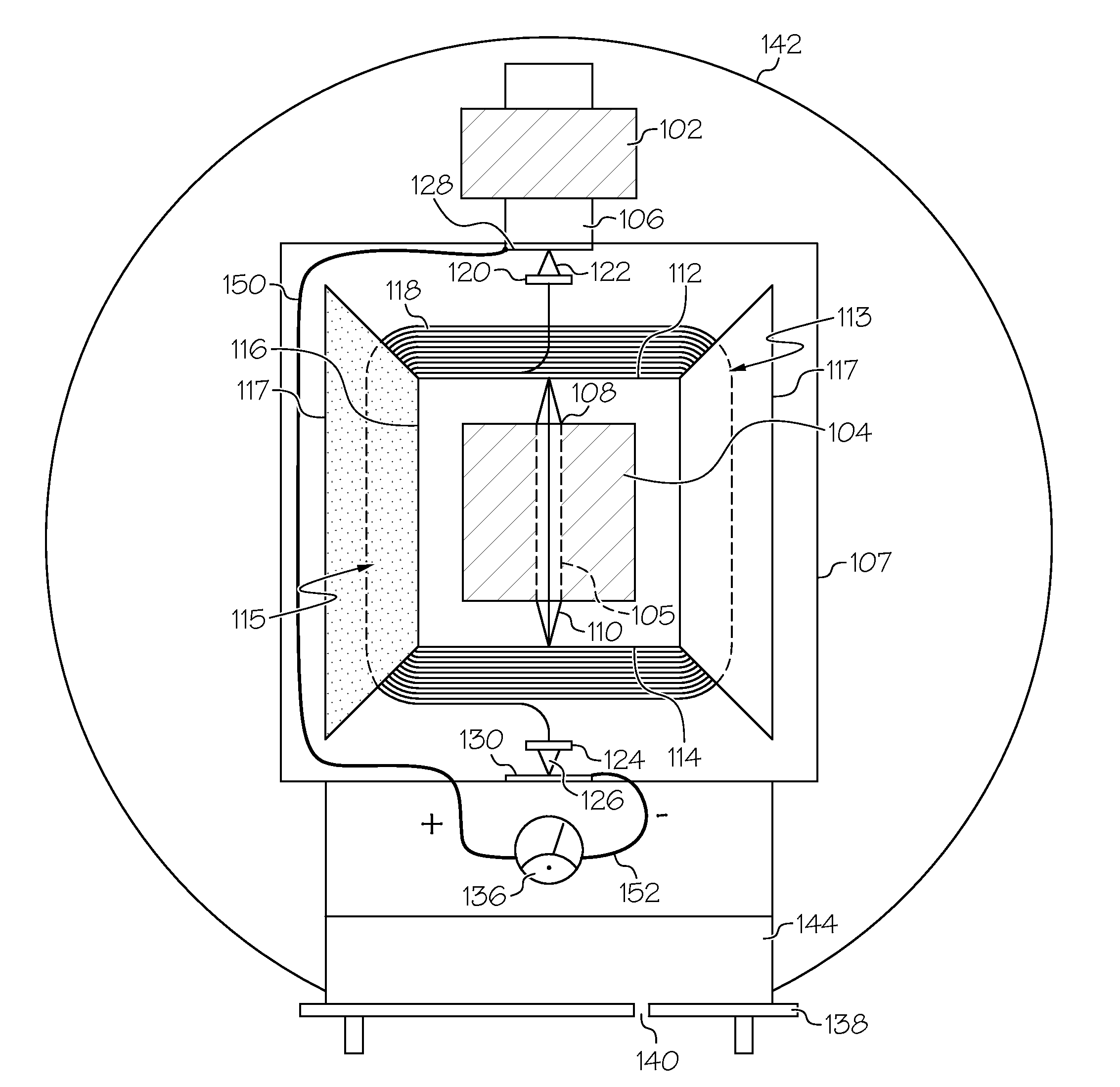
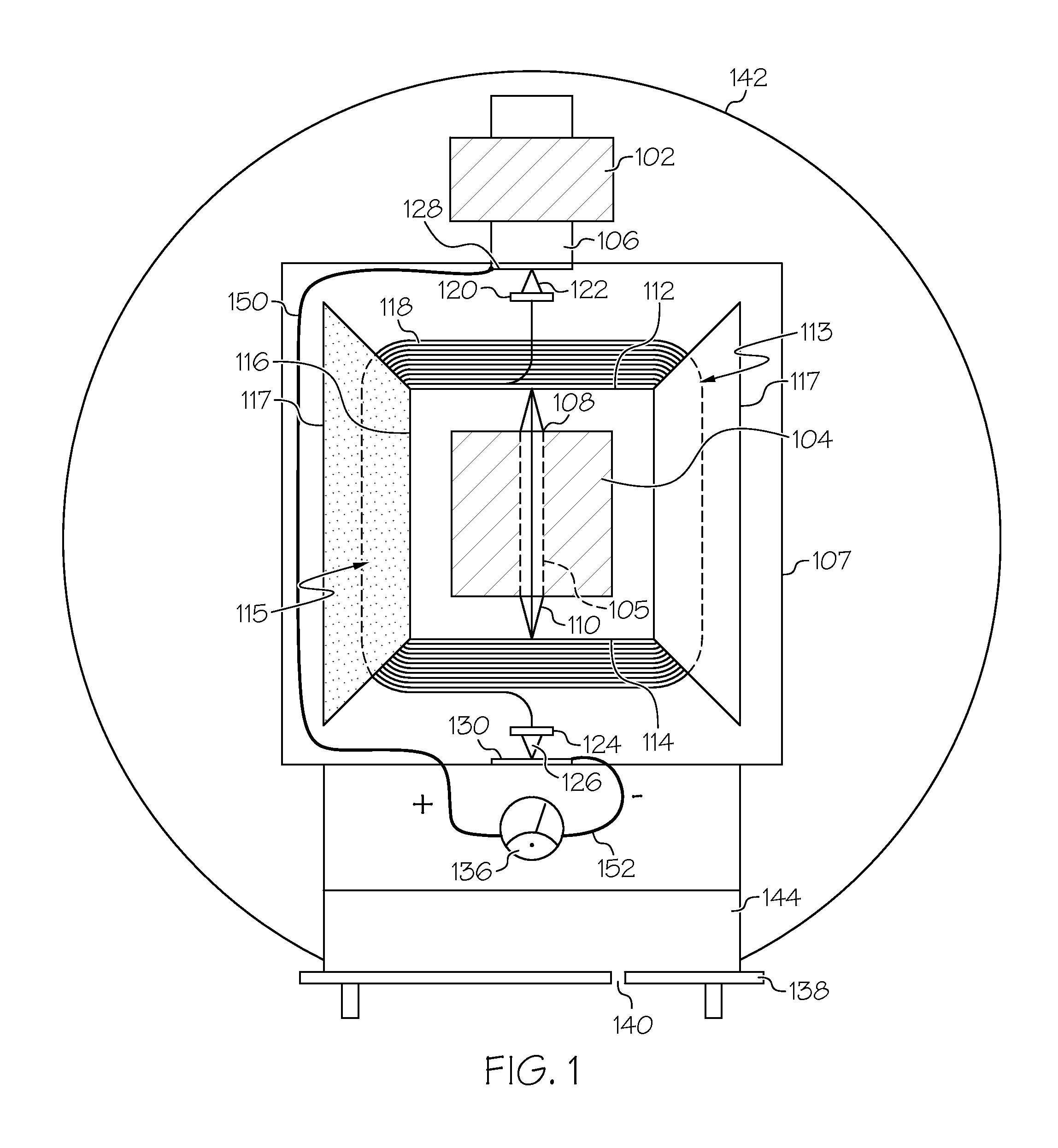
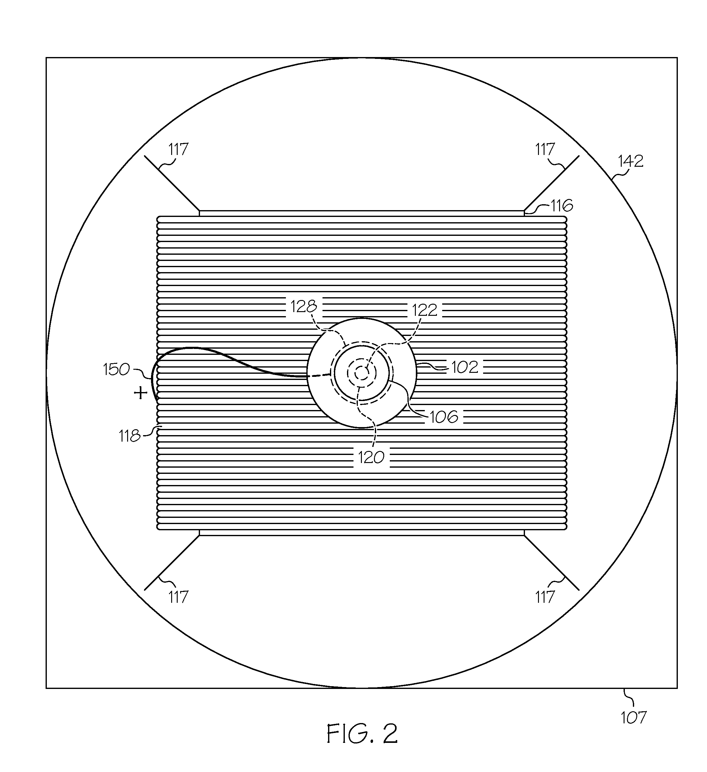
[0014]Illustrative embodiments will now be described more fully herein with reference to the accompanying drawings, in which embodiments are shown. This disclosure may, however, be embodied in many different forms and should not be construed as limited to the embodiments set forth herein. Rather, these embodiments are provided so that this disclosure will be thorough and complete and will fully convey the scope of this disclosure to those skilled in the art. In the description, details of well-known features and techniques may be omitted to avoid unnecessarily obscuring the presented embodiments.

[0015]The terminology used herein is for the purpose of describing particular embodiments only and is not intended to be limiting of this disclosure. As used herein, the singular forms “a”, “an”, and “the” are intended to include the plural forms as well, unless the context clearly indicates otherwise. Furthermore, the use of the terms “a”, “an”, etc., do not denote a limitation of quantity,...


PUM


Abstract

An electric radiometer generates electricity in tangible amounts by placing stationary rare earth magnets on a stationary magnetized needle which are connected to two-sided aluminum wings in such a manner that an electric current is produced when the coils in motion cut across the flux lines of a stationary magnetic field after a complete revolving circuit to a receiving device.

Description

CROSS REFERENCE TO RELATED APPLICATIONS[0001]This application claims priority to U.S. Provisional Patent Application No. 61 / 735,770, filed Dec. 11, 2012 and U.S. Provisional Patent Application No. 61 / 819,040, filed May 3, 2013. The aforementioned provisional patent applications are hereby incorporated by reference in their entirety. In addition, this application is related in some aspects to commonly-owned and co-pending application number (Attorney Docket No. SOLA-0004), entitled “WINDMILL GENERATOR”, filed on May 23, 2013, the entire contents of which are herein incorporated by reference.FIELD OF THE INVENTION[0002]The present invention relates to a method and apparatus for generating electricity, and more particularly, to a method and apparatus for generating electricity from solar energy.BACKGROUND OF THE INVENTION[0003]The radiometer has been regarded since the 19th Century as a scientific novelty. Invented by Sir William Crooks, the radiometer generally consists of a set of va...

Claims


Application Information

Patent Timeline
IPC IPC(8): H02K7/18
CPCH02K7/1807H02K21/26H02K7/09H02K7/183F03D3/061F05B2220/7068Y02E10/74Y02E10/72
Inventor FARQUHARSON, ASTON GUSTAVOUSMOUSAA, VICTOR ROLAND VARGAS
Owner NUSPECIES GLOBAL MACHINES
Why Eureka
Try Eureka