Imaging apparatus and camera including the same

a technology which is applied in the field of imaging apparatus and camera, can solve the problems that the vibration of the actuator due to the expansion and contraction of the actuator has little effect in shaking off dust, and achieve the effect of efficient removal of dus

Active Publication Date: 2014-06-12
SAMSUNG ELECTRONICS CO LTD
View PDF27 Cites 9 Cited by
  • Summary
  • Abstract
  • Description
  • Claims
  • Application Information

AI Technical Summary

Benefits of technology

[0011]Various embodiments provide an imaging apparatus that may efficiently remove dust adhering to a surface of an optical element disposed in front of an imaging element and may change the position of the imaging element, and a camera including the imaging apparatus.

Problems solved by technology

Accordingly, when dust adheres to a surface of the imaging element or a surface of a transparent member disposed in front of the imaging element, shadows due to the dust are generated on a generated image, which becomes a problem.
However, according to the technology of Document 1, a mechanism to displace the imaging element is provided separately because there is no means to displace the position of the imaging element.
However, since the protection glass vibrates in a direction parallel to a surface of the protection glass in this technology, the vibration due to the expansion and contraction of the actuator has little effect in shaking the dust off.

Method used


Image

  • Imaging apparatus and camera including the same
  • Imaging apparatus and camera including the same
  • Imaging apparatus and camera including the same

Examples


1st embodiment

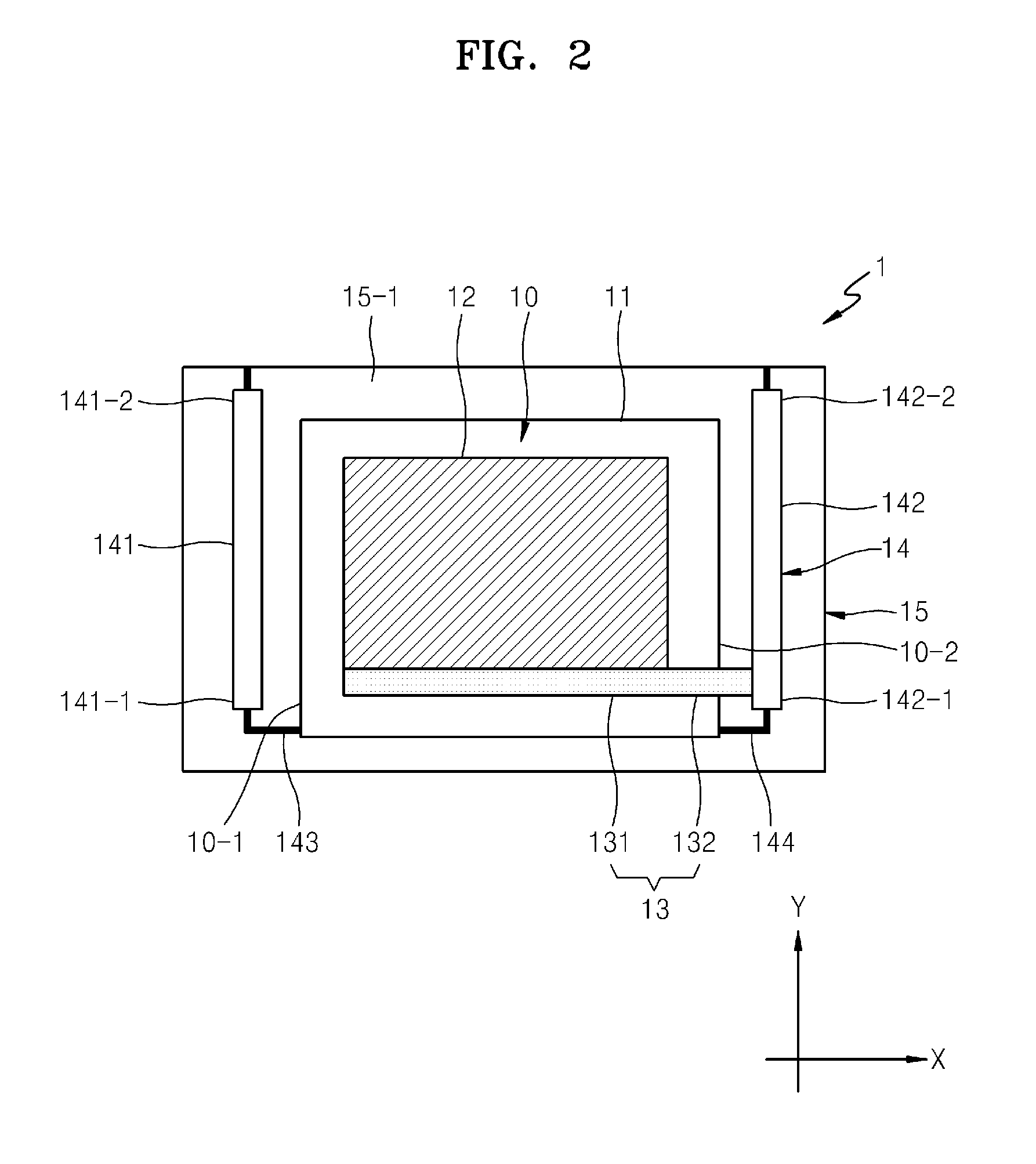
[0028]FIGS. 2 to 4 are diagrams illustrating an imaging apparatus 1, according to an embodiment. Referring to FIG. 2, the imaging apparatus 1 includes a first frame 15, an imaging element unit 10 supported by the first frame 15 to be displaceable or movable, a displacement increment mechanism 14 that connects the first frame 15 and the imaging element unit 10, and a piezoelectric element 13, as a first piezoelectric element, that connects the imaging element unit 10 and the displacement increment mechanism 14.

[0029]The first frame 15 may have, for example, a rectangular frame structure having a hollow portion therein. The imaging element unit 10 and the displacement increment mechanism 14 may be arranged inside the first frame 15.

[0030]The imaging element unit 10 includes an optical element 12 that is integrally formed with an imaging element 11. The imaging element 11 includes a plurality of photoelectric conversion elements arranged in a plate shape. For example, the imaging eleme...

2nd embodiment

[0042]FIG. 5 is a diagram illustrating an imaging apparatus 2, according to another embodiment. Referring to FIG. 5, the imaging apparatus 2 according to the present embodiment further includes a piezoelectric element 17 as a second piezoelectric element and a second frame 18 as a support portion disposed outside the first frame 15. For example, the second frame 18 has a rectangular frame larger than the first frame 15. The first frame 15 may be arranged inside the second frame 18. One end of the piezoelectric element 17 is connected to the outside surface of the upper frame 15-1 of the first frame 15. The other end of the piezoelectric element 17 is connected to the inside surface of an upper frame 18-1 of the second frame 18. The piezoelectric element 17 is driven or controlled by DC power to expand / contract in the Y-axis direction.

[0043]According to the present embodiment, as the piezoelectric element 17 of the imaging apparatus 2 is driven or controlled by DC power, the piezoele...

3rd embodiment

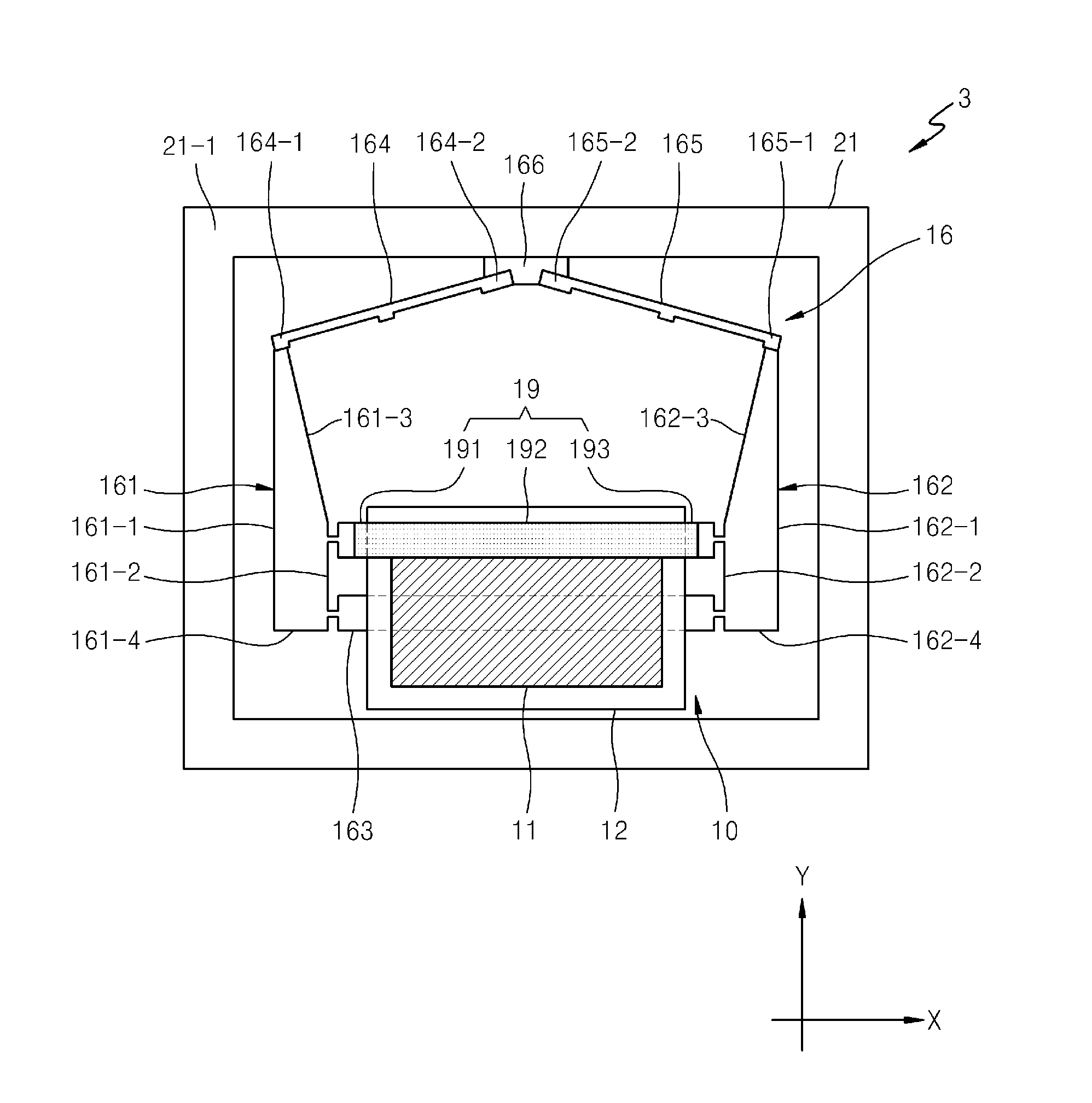
[0045]FIG. 6 is a diagram illustrating an imaging apparatus 3, according to another embodiment. Referring to FIG. 6, the imaging apparatus 3 includes a first frame 21, the imaging element unit 10 supported on the inside of the first frame 21 to be displaceable or movable, a displacement increment mechanism 16 is disposed inside the first frame 21 and connects the first frame 21 and the imaging element unit 10, and a piezoelectric element 19, as a first piezoelectric element, is connected between the imaging element unit 10 and the displacement increment mechanism 16.

[0046]The displacement increment mechanism 16 includes a first link 161, a second link 162, a support link 163, a first operation link 164, a second operation link 165, and an operation member 166. The displacement increment mechanism 16 has a roughly or substantially pentagonal shape with the support link 163 as a base.

[0047]The first and second links 161 and 162 each have a roughly or substantially trapezoidal shape. T...


PUM


Abstract

An imaging apparatus includes an imaging element unit having an imaging element and an optical element which is integrally formed with the imaging element and through which a luminous flux of light for imaging passes, a first piezoelectric element, and a displacement increment mechanism connected to the first piezoelectric element and the imaging element unit. The displacement increment mechanism displaces the imaging element unit by expanding or contracting the first piezoelectric element, where a portion of the first piezoelectric element in a lengthwise direction thereof is attached to the optical element.

Description

CROSS-REFERENCE TO RELATED PATENT APPLICATIONS[0001]This application claims the priority benefits of Japanese Patent Application No. 2012-268272, filed on Dec. 7, 2012, in the Japanese Patent Office, and Korean Patent Application No. 10-2013-0066059, filed on Jun. 10, 2013, in the Korean Intellectual Property Office, the disclosures of which are incorporated herein in their entirety by reference.BACKGROUND[0002]1. Field[0003]Various embodiments of the invention relate to an imaging apparatus and a camera including the imaging apparatus.[0004]2. Related Art[0005]In an imaging apparatus, a luminous flux of light passing through a lens is received by an imaging element (e.g., a charge coupled device (CCD) image sensor), and image data is generated by processing a photoelectric conversion output of the imaging element. As a pixel pitch of an imaging element decreases, the quality of an image provided by the imaging apparatus is remarkably improved. Accordingly, when dust adheres to a su...

Claims


Application Information

Patent Timeline
Patent Type & Authority Applications(United States)
IPC IPC(8): H04N5/225G03B17/12
CPCH04N23/811H04N23/54H04N25/48
Inventor KOMADA, JUNSHIRONO, MASAHIRO
Owner SAMSUNG ELECTRONICS CO LTD
Why Eureka
Try Eureka