Turbo-machine component and method

a technology of turbine machine and component, which is applied in the direction of machines/engines, manufacturing tools, liquid fuel engines, etc., can solve the problems of inability to meet the requirements of the operating environment,

Inactive Publication Date: 2014-06-12
GENERAL ELECTRIC CO
View PDF10 Cites 29 Cited by
  • Summary
  • Abstract
  • Description
  • Claims
  • Application Information

AI Technical Summary

Benefits of technology

[0007]A component, a component manufacturing process, and a component operation process that do not suffer from one or more of the above drawbacks would be desirable in the art.
[0008]In an exemplary embodiment, a component has a diffuser that includes a first region having a first section with a first cross-sectional area, a second region having a second section with a second cross-sectional area that is greater than the first cross-sectional area, a coating collection feature at least partially positioned within the second region, and a flow-path arranged and disposed to permit compressible fluid to flow throughout the first region and the second region of the diffuser at a decreasing velocity.
[0009]In another exemplary embodiment, a component-man...

Problems solved by technology

Prior attempts to use coatings on surfaces outside of diffusers but still proximal to the diffusers have resulted in such clogging or otherwise modifying of the internal profiles of the diffusers.
For example, such attempts resulted in constrictions of flow-pa...

Method used


Image

  • Turbo-machine component and method
  • Turbo-machine component and method
  • Turbo-machine component and method

Examples


Embodiment Construction

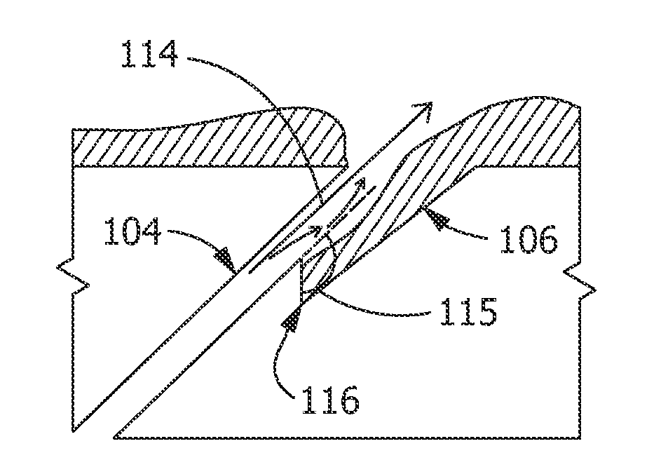
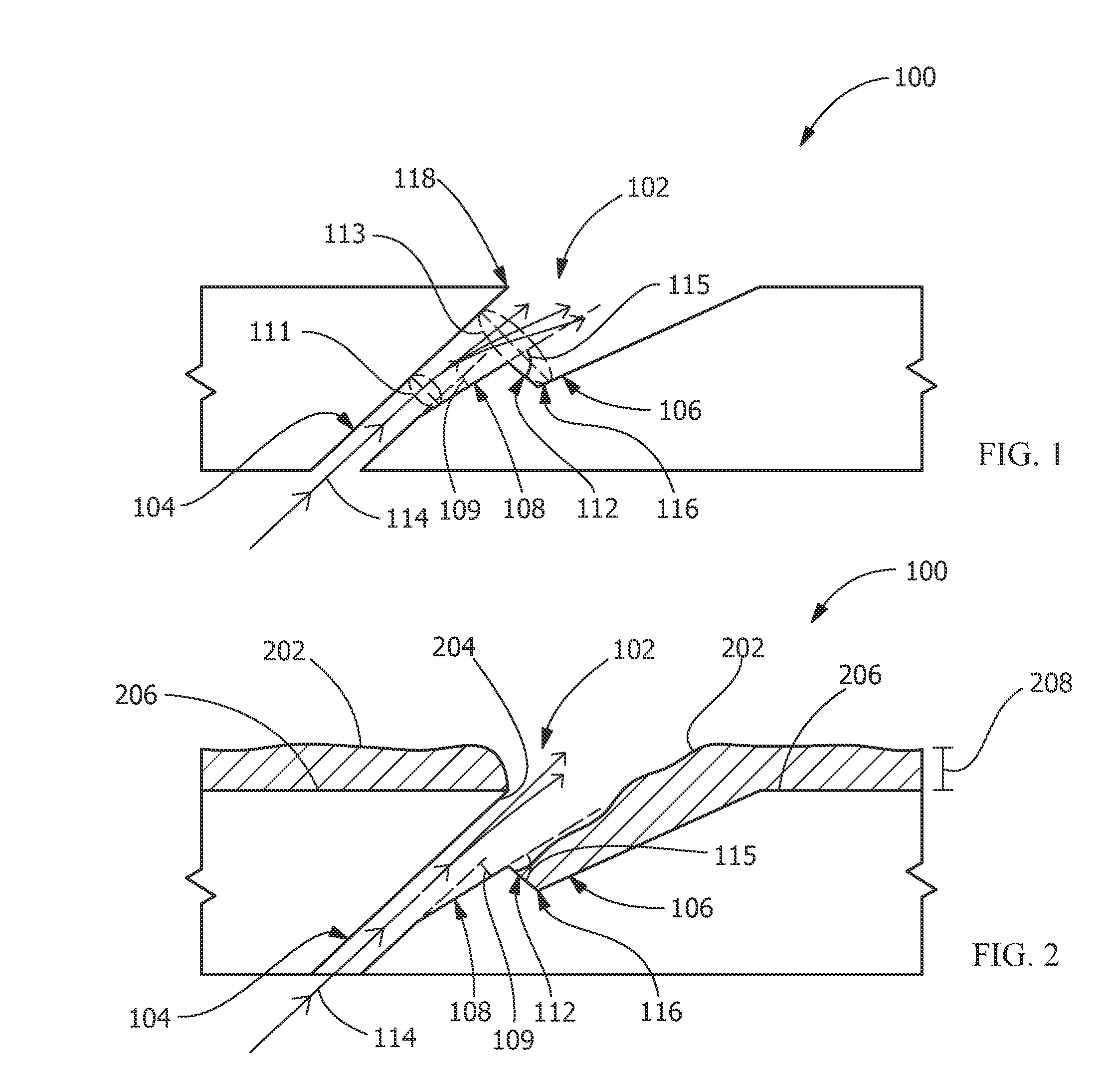
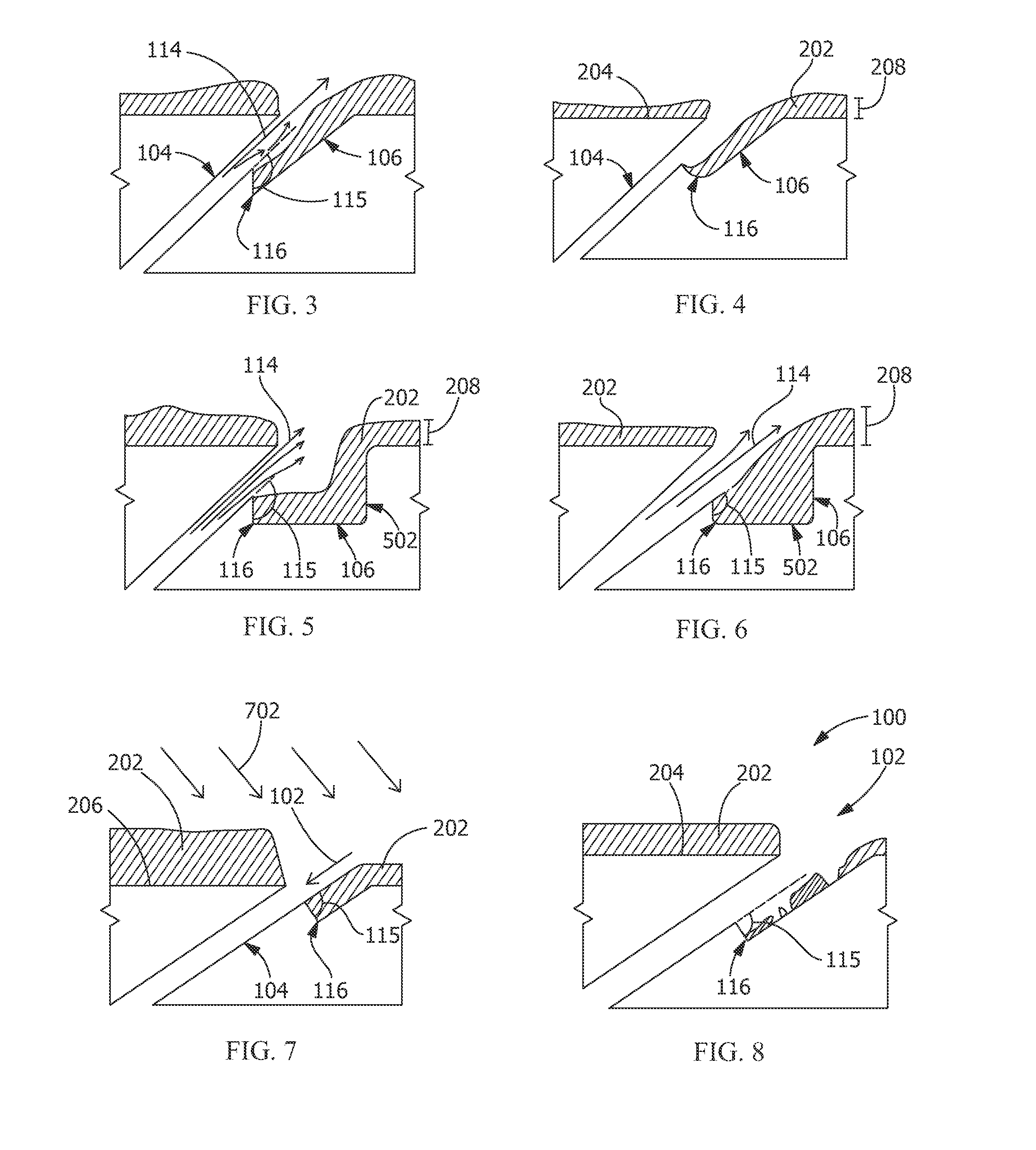
[0023]Provided is an exemplary component, a component manufacturing process, and a component operation process. Embodiments of the present disclosure permit airflow for cooling components, reduce or eliminate partial or complete blockages of diffusers, permit operation in more harsh environments (for example, environments having greater thermal gradients), permit additional control of fluid flow-paths and / or fluid velocity profiles within diffusers, facilitate a controlled decrease in velocity of compressible fluids within diffusers, increase operational efficiencies, or combinations thereof.

[0024]FIG. 1 shows a portion of a component 100 according to an embodiment of the disclosure. The component 100 is any suitable article for transport of a fluid. For example, in one embodiment, the component 100 is a turbine component, such as, a turbine blade 902 (see FIG. 9), a nozzle 910 (see FIG. 10), or any other article containing one or more diffusers 102 for transporting a fluid, such as...


PUM

PropertyMeasurementUnit
Thicknessaaaaaaaaaa
Thicknessaaaaaaaaaa
Thicknessaaaaaaaaaa

Abstract

A component, a component manufacturing process, and a component operation process are disclosed. The component has a diffuser permitting compressible fluid to flow throughout a first region and a second region of the diffuser at a decreasing velocity. The diffuser includes a coating collection feature. The component manufacturing process includes positioning the component and applying the coating to at least a surface of the component outside of the diffuser and to at least a portion of the second region, not to the first region, to the coating collection feature, or a combination thereof. The component operation process includes positioning the component and transporting the compressible fluid through the diffuser.

Description

STATEMENT REGARDING FEDERALLY SPONSORED RESEARCH OR DEVELOPMENT[0001]The United States Government retains license rights in this invention and the right in limited circumstances to require the patent owner to license others on reasonable terms by the terms of Government Contract No. 9FB-05 awarded by the United Stated Department of Energy.FIELD OF THE INVENTION[0002]The present invention is directed to components, processes of manufacturing components, and processes of operating components. More specifically, the present invention relates to components and processes involving diffusers.BACKGROUND OF THE INVENTION[0003]Diffusers permit airflow to and from systems relying upon air flow. For example, diffusers cool components or portions of components subjected to high temperature due to operation of the component, the environment of the component, or combinations thereof. For example, diffusers in turbine blades cool the blades, which operate under extreme temperatures during power ge...

Claims


Application Information

Patent Timeline
IPC IPC(8): F01D9/02
CPCF01D9/02F01D5/186F05D2230/90F05D2240/304F01D5/288Y10T29/49826
Inventor ARNESS, BRIAN PETERMEYER, ROBERTAMMANN, LISA
Owner GENERAL ELECTRIC CO
Why Eureka
Try Eureka