Terrain surveillance system

a surveillance system and surveillance technology, applied in surveying and navigation, distance measurement, instruments, etc., can solve the problems of limited screening capabilities, high false alarm rate, limited widespread deployment, etc., and achieve low false alarm rate, low capital cost, and high sensitivity

Active Publication Date: 2014-06-19
SHILAT OPTRONICS
View PDF4 Cites 28 Cited by
  • Summary
  • Abstract
  • Description
  • Claims
  • Application Information

AI Technical Summary

Benefits of technology

[0007]The present disclosure describes new exemplary systems for the surveillance of terrain and the detection of intrusions over a plane extending into that terrain, combining low capital cost and high sensitivity with a low false alarm rate (FAR). The systems are based on the generation of a curtain array of light beams projected along a plane extending into the field to be surveilled, and the detection of the distance and height of any reflection from this array of light beams, by means of a detection array, detecting imaged fields of view along that plane within the field of view surveilled. Such reflections arise from impingements of the beams with objects along the plane being surveilled by the detector imaging array. Since the initial background reflection pattern without any intrusion can be acquired and stored by the system, a sudden change in this detected background pattern can be defined as arising from an unexpected reflection, and hence indicative of an intrusion. Slow changes can be attributed to gradual changes in the background and can be ignored. The systems described herewithin utilize the times of flight of the laser beams, from transmission to detection, in order to characterize the form of the terrain being surveilled.
[0008]The angular direction from which the reflection originates is known from the knowledge of which particular detector pixel has detected the reflection signal, since each pixel is directed to monitor a different angular direction of the field of view. The longitudinal position along the line of detection from which the reflection is generated is known from the time of flight of the laser beam reflected into that detector pixel. Since each laser beam in the curtain is directed at a specific direction in the plane, and each detector pixel is also directed at its own specific direction in the plane, each pixel can be uniquely associated with a specific laser beam, and is essentially bore-sighted with its associated laser beam. Thus, the time of flight of each laser beam, from transmission from the source to the detection of the reflection of that beam by its own associated detector pixel, enables the longitudinal position from which the reflection took place to be determined. Thus, measurement of a change in the time of flight of a beam as detected at its associated pixel, enables the distance of an intrusion to be determined, and the height above the terrain level can be determined by knowledge of the specific beam in which the change in time of flight has been detected. The time of flight may be conveniently determined by measuring the change in phase of the modulated laser beam between it transmission and its detection.
[0018]The signal processing unit in any of such systems may further be adapted to detect changes in the intensity of light reflected from the plurality of angularly divergent optical paths, and to temporally correlate any intensity changes detected with changes in the time of flights, such that the intrusion detection can be determined with increased reliability.
[0019]Additional implementations may involve systems such as are described above in which the illuminating beams are modulated at a predetermined frequency, and the array of detector elements is configured to image the reflected light at a rate which is a multiple of the predetermined frequency, and wherein the signal processing unit is adapted to subtract signals arising from samples temporally separated from each other by half of the modulation period, such that the subtraction signal is representative of the reflected light from a detected object in the optical paths without the effect of any background illumination. In such a system, the signals temporally separated from each other by half of the modulation period may be accumulated in separate CCD charge registers, such that the accumulated signals can be read out at a rate substantially lower than the predetermined modulation frequency. Furthermore, the subtracted signals arising from samples temporally separated from each other by half of the modulation period, enable the subtraction of signals arising from background illumination from signals arising from the reflected laser beams.
[0028]The above described methods may include the further step of detecting changes in the intensity of light reflected from the plurality of optical paths, and temporally correlating any intensity changes detected with the changes in the time of flights, such that the intrusion detection can be determined with increased reliability.

Problems solved by technology

Current solutions based on video camera imaging, and using signal processing to detect changes in those images, generally have a number of disadvantages which have limited their widespread deployment, especially for border use over long distances, or in regions where the terrain is rough.
Such video systems may have high false alarm rates (FAR), limited capabilities for screening irrelevant intrusions such as by animals, significant power consumption, and they could be costly in capital expenses.
However, a large value of d means that the laser array and the detector array must be widely spaced, and the physical size of the instrument must also be large, and this may make the system cumbersome to install and use, and easy to detect by a potential intruder.

Method used


Image

  • Terrain surveillance system
  • Terrain surveillance system
  • Terrain surveillance system

Examples


Embodiment Construction

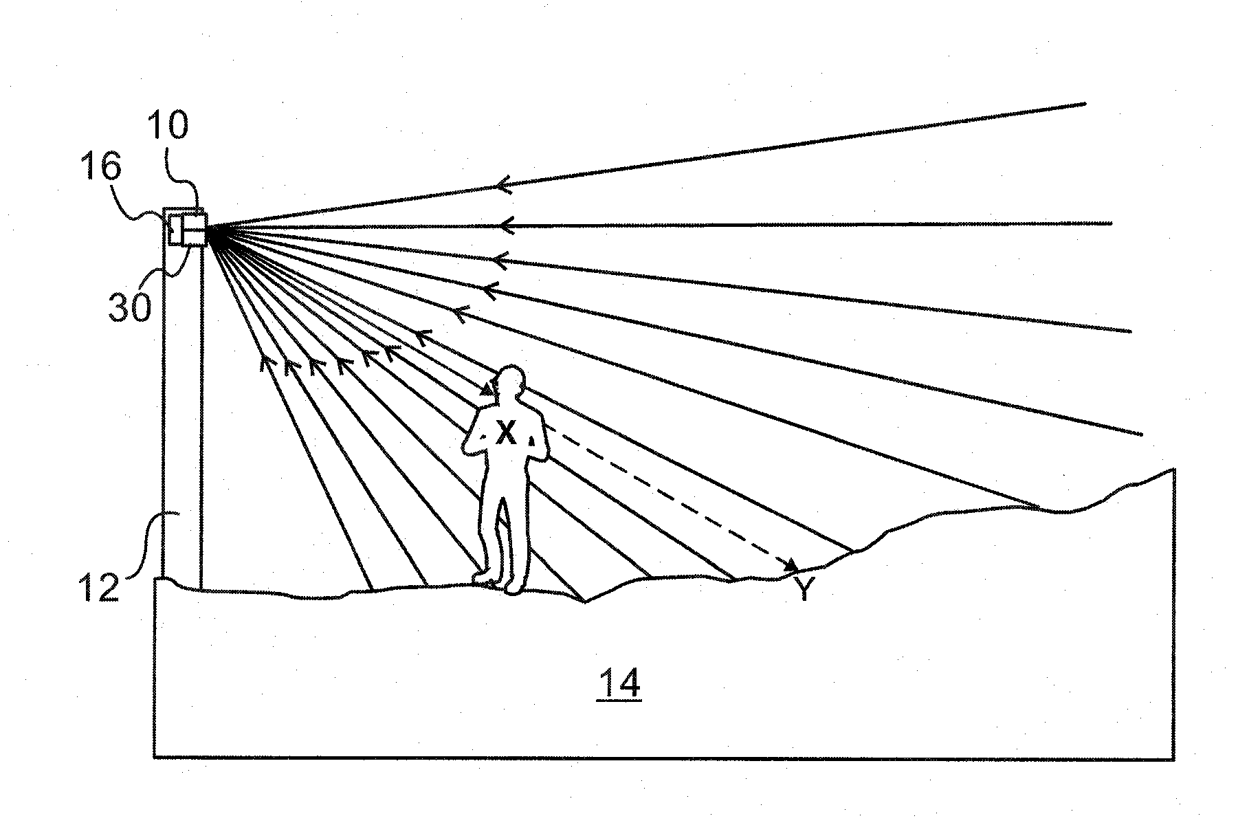
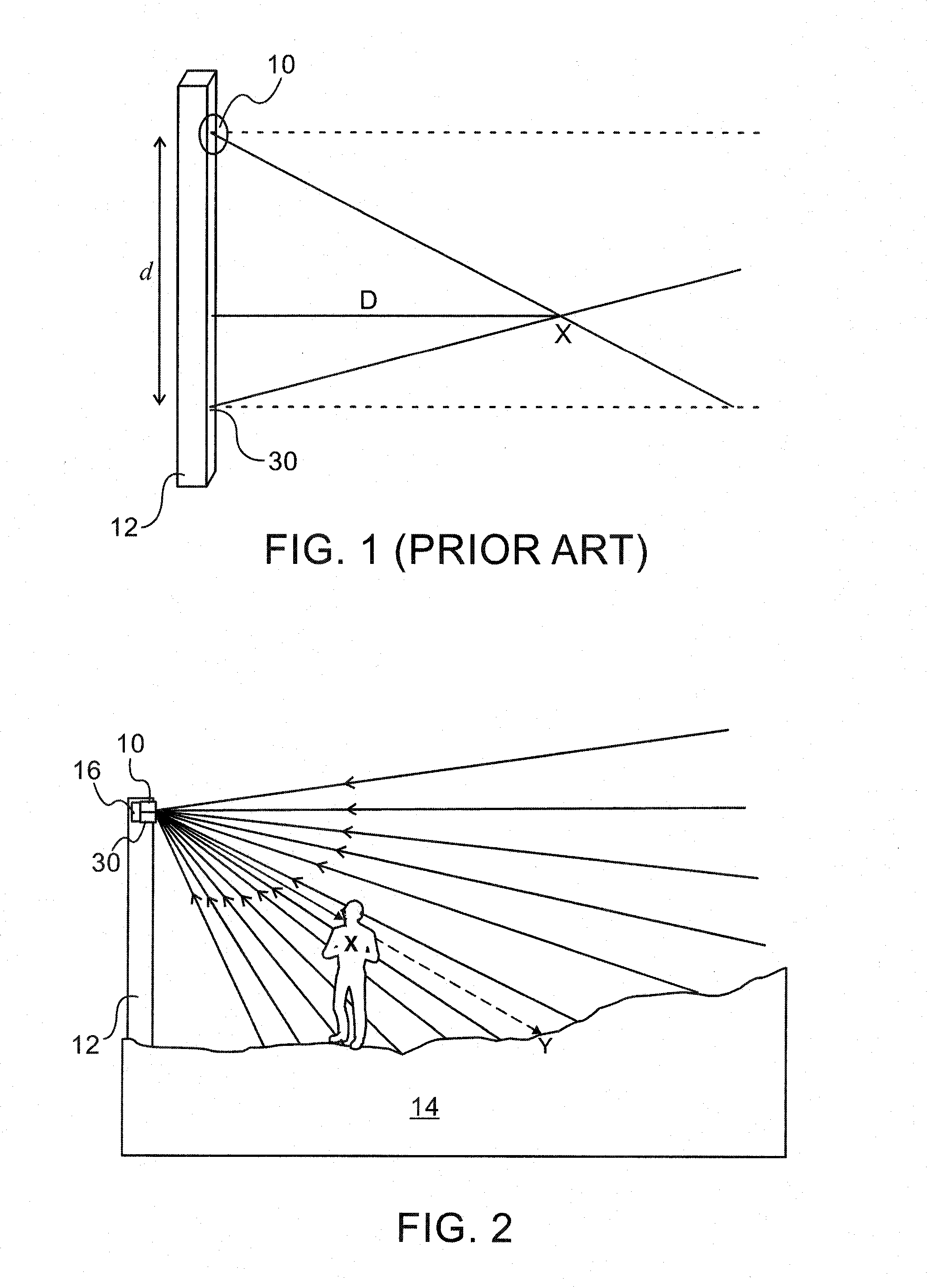
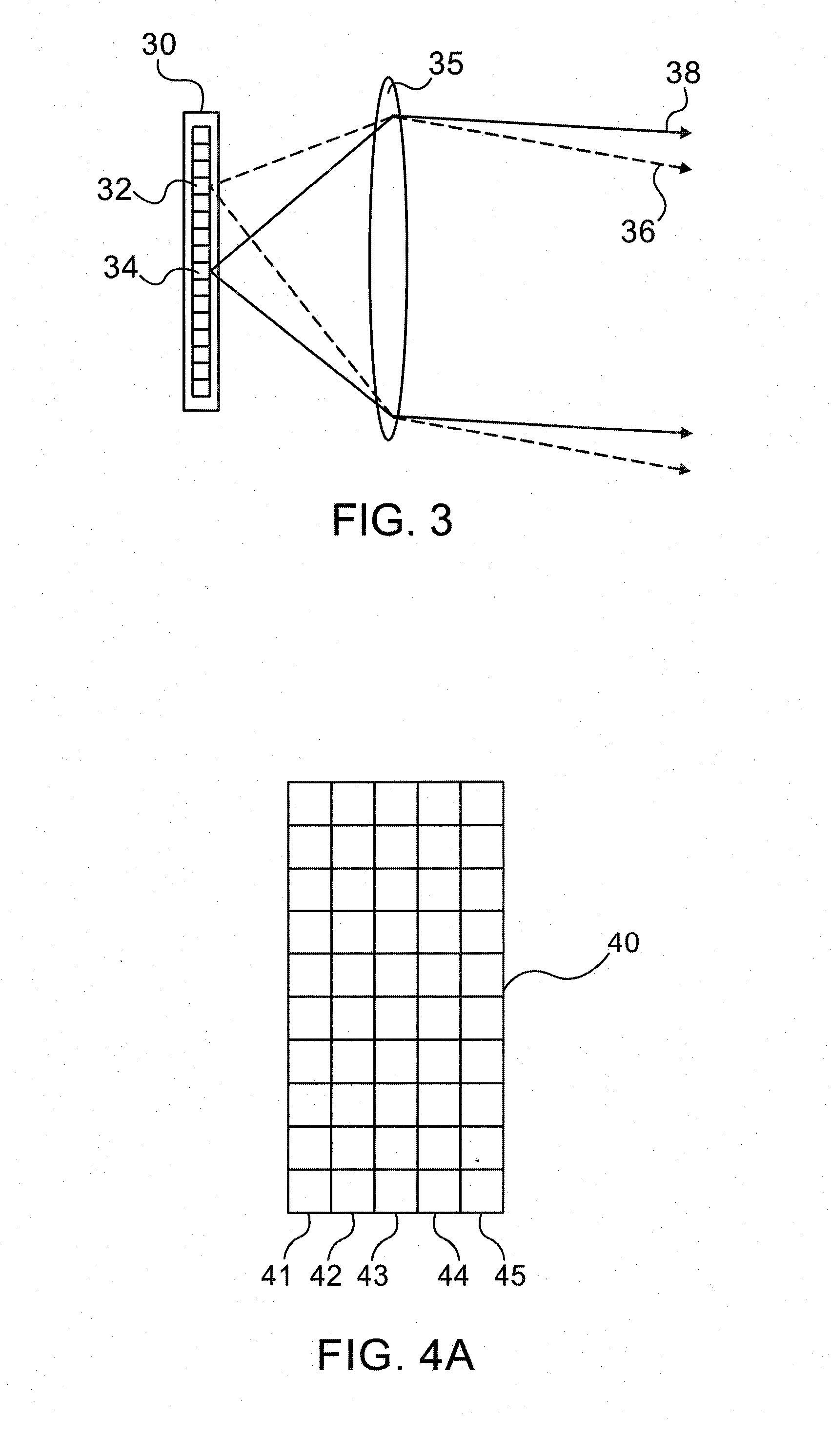
[0042]Reference is made to FIG. 2, which illustrates an exemplary system for intrusion detection or terrain surveillance and mapping, using two features—an array of projected laser beams, propagating in the form of a curtain, and an array of detectors, each element of which is directed to detect light received from a particular field of view in the terrain to be surveilled. Individual pixels in the detector array are directed at specific angular locations in the field of view, such that each detector pixel is associated with a corresponding one of the array of laser sources. Thus, each individual laser source is aimed at its own specific angular direction, and each individual pixel of the detector array images light coming from its own specific angular direction, such that each pixel is known to image only light reflected from the point of impingement of the laser beam associated with the direction of that pixel. These two features are jointly able to define which beam has impinged ...


PUM


Abstract

A system for the surveillance of terrain and the detection of intrusions over a plane extending into that terrain. A curtain array of light beams is projected along the plane and reflections from the terrain are detected by a sensor array essentially spatially coincident with the array of light sources. The times of flight of the beams are determined, and these characterize the form of the terrain being surveilled. The initial background reflection pattern is acquired and stored by the system. A sudden change in this detected background pattern can be defined as arising from an unexpected reflection, indicative of an intrusion. Signal processing systems are described utilizing modulated laser beams and detection at a frequency at least twice that of the modulation, such that reflected signals arising from the ON and the OFF periods of the laser modulation can be subtracted to eliminate the background signals.

Description

[0001]The present invention relates to the field of the surveillance of terrain in order to map and measure that terrain, and thereby to detect unauthorized intrusion within that terrain, especially using optical techniques.BACKGROUND OF THE INVENTION[0002]Virtual fencing may be used for protecting or securing a separation line against intrusion by unwanted persons or objects in applications where a physical fence is inadequate or impractical, such as over long distances or where the terrain is too rough, or the cost is too high. The virtual fence could be used to protect a border, or the perimeters of an enclosed security area such as an airport, a strategic site, a hospital or university campus, fields and farms, or even private houses and estates The virtual fence should provide warning about the intended intrusion, and should be able to provide information about the location and type of intrusion expected. Current solutions based on video camera imaging, and using signal process...

Claims


Application Information

Patent Timeline
Patent Type & Authority Applications(United States)
IPC IPC(8): G08B13/189
CPCG08B13/189G08B13/184
Inventor GUETTA, AVISHAYYAGUDAEV, MICHAELKORNGUT, DORON
Owner SHILAT OPTRONICS
Why Eureka
Try Eureka