Ionizing pump stage

a technology of ionizing pump and pump stage, which is applied in the direction of pump components, positive displacement liquid engines, particle separator tubes, etc., can solve the problems of correspondingly complicated and/or expensive manufacture of these components, and achieve the effect of effective acceleration, ho factor and idling compression of the pump stage, and effective acceleration

Active Publication Date: 2014-06-19
PFEIFFER VACUUM GMBH
View PDF2 Cites 5 Cited by
  • Summary
  • Abstract
  • Description
  • Claims
  • Application Information

AI Technical Summary

Benefits of technology

[0011]It has been found that a pump stage having the above-described simple design in particular also achieves an efficient pumping effect for light gases which results in a very high suction capacity of the pump stage which can amount to a multiple of the suction capacity of a turbomolecular pump so that an accordingly high Ho factor and a high idling compression of the pump stage can be achieved.
[0039]In accordance with an advantageous embodiment, the at least one ionizing pump stage is followed in the conveying direction by at least one further pump stage which is preferably connected in series to the ionizing pump stage in a gas-conveying manner, with the further pump stage being able to serve as a roughing stage with respect to the ionizing pump stage. The further pump stage is particularly preferably configured as a turbomolecular pump stage. It has been found that a vacuum pump having excellent pump properties and in particular a substantially increased suction capability and an increased idling compression in comparison with a purely turbomolecular pump stage can be provided by the combination of the ionizing pump stage with a downstream turbomolecular pump stage, and indeed substantially independently of the molecular mass of the conveyed gas molecules.

Problems solved by technology

Furthermore, in particular those vacuum pumps which are suitable for producing a very high vacuum have a complex design so that their manufacture is correspondingly complicated and / or expensive.

Method used


Image

  • Ionizing pump stage
  • Ionizing pump stage
  • Ionizing pump stage

Examples


Embodiment Construction

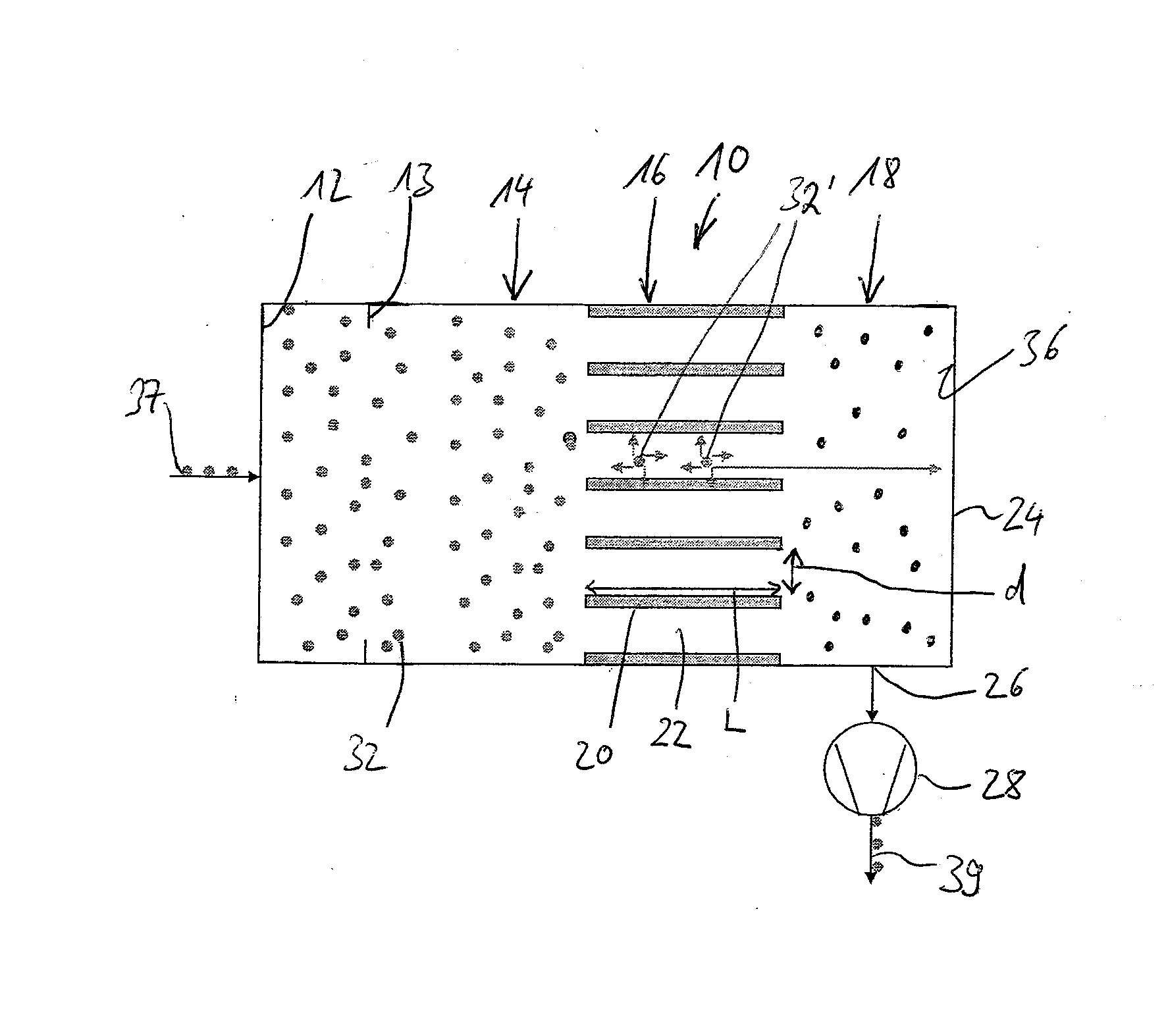
[0045]FIG. 1 shows a vacuum pump having an ionizing pump stage 10 in accordance with an embodiment of the invention.

[0046]The ionizing pump stage 10 comprises an inlet 12 through which the gas can enter from a volume to be evacuated into the conveying space of the ionizing pump stage 10. A plurality of gas molecules are shown by way of example and as exaggeratedly large in FIG. 1 and are provided with the reference numeral 32 and 32′ respectively. A gas molecule 32, 32′ is in principle also to be understood as a single gas atom. Accordingly, an ionized gas molecule 32, 32′ is to be understood both as an ionized gas molecule, i.e. a gas molecule electrically charged once or a multiple of times, comprising a plurality of atoms and also as an ionized gas atom.

[0047]Following the inlet 12 in the conveying direction, a baffle 13 is provided with which the cross-section of the conveying space and thereby the amount of the gas can be regulated which enters into the sections of the conveyin...


PUM


Abstract

The invention relates to an ionizing pump stage, in particular for a vacuum pump, comprising an inlet for gas entering into the pump stage; an ionizing section communicating with the inlet in a gas-conductive manner and an ionizing device for ionizing the gas entered into the ionizing section; an acceleration device for accelerating the ionized gas present in the ionizing section in the conveying direction; and a neutralizing section following the ionizing section in the conveying direction and communicating with the ionizing section in a gas-conductive manner and a neutralizing device for the electrical neutralizing of the ionized gas entering into the neutralizing section.

Description

BACKGROUND OF THE INVENTION[0001]1. Field of the Invention[0002]The present invention relates to an ionizing pump stage, in particular for a vacuum pump.[0003]2. Description of the Prior Art[0004]Different types of vacuum pumps and of pump stages for vacuum pumps are known which differ e.g. with respect to their suction capacities and the minimal vacuum pressures which can be produced. Turbomolecular pumps, cryopumps, ion getter pumps and titanium sublimation pumps represent conventional vacuum pumps, for example. The maximum suction capacity and accordingly the Ho factor which is given by the quotient of the maximum suction capacity and the inlet admittance of the pump are restricted in the turbomolecular pumps in particular used in the high vacuum area for producing very low vacuum pressures. In addition, the suction capacity and thus the Ho factor of these pumps depend on the molecular mass of the pumped gases and decrease as the molecular mass decreases, i.e. only a lower suctio...

Claims


Application Information

Patent Timeline
Patent Type & Authority Applications(United States)
IPC IPC(8): F15D1/00
CPCH01J41/12F15D1/0075
Inventor CONRAD, ARMIN
Owner PFEIFFER VACUUM GMBH
Why Eureka
Try Eureka