High Flow Volume Nasal Irrigation Device and Method for Alternating Pulsatile and Continuous Fluid Flow

a technology of pulsatile and continuous fluid flow, which is applied in the direction of enemata/irrigators, other medical devices, physical therapy, etc., can solve the problems of ineffective continuous stream devices, inability to rehabilitate nasal cilia which have lost motility, and less than optimal cleaning ability of devices

Inactive Publication Date: 2014-06-19
CARPENTER MARK
View PDF18 Cites 9 Cited by
  • Summary
  • Abstract
  • Description
  • Claims
  • Application Information

AI Technical Summary

Benefits of technology

[0007]A high flow volume nasal irrigation device for pulsatile and continuous fluid flow is disclosed. The device includes a chamber having a reservoir of liquid and a volume of air. The chamber is configured to elastically deform in response to an applied pressure and thus pressurize the liquid and air therein. The device also includes a fluid conduit configured to convey a pressurized liquid flow from a first end inside the chamber to a second end outside the chamber at a lower pressure. At least one air metering orifice is formed in the fluid conduit. The air metering orifice is configured to introduce a plurality of air pockets from the air volume into the liquid flow and thus generate a pulsatile fluid flow in the conduit.
[0008]A disclosed high flow volume nasal irrigation device allows a user to alternate pulsatile and continuous fluid flow. The device may also include a squeeze bottle with an open end, a reservoir of liquid and a volume of air. The squeeze bottle is configured to elastically deform in response to a manual pressure from a user and thus pressurize the liquid and air. The device also includes a dip tube configured to convey a pressurized liquid flow from a first end inside the squeeze bottle to a second end outside the squeeze bottle. The second end comprises a void in the tube wall. A removable nipple cap is also included, the cap connected to the squeeze bottle open end.

Problems solved by technology

Unfortunately, these devices offer a less than optimal cleaning ability due to the tendency of the continuous stream to form laminar flow paths across the surfaces to be rinsed and due to the surfaces not being deformed and agitated by the smooth flow stream.
These continuous stream devices are also ineffectual in projecting liquid medications or irrigants into sinus cavities because the closed end cavities require time varying pressures to cause fluid entry.
They also fail to rehabil

Method used


Image

  • High Flow Volume Nasal Irrigation Device and Method for Alternating Pulsatile and Continuous Fluid Flow
  • High Flow Volume Nasal Irrigation Device and Method for Alternating Pulsatile and Continuous Fluid Flow
  • High Flow Volume Nasal Irrigation Device and Method for Alternating Pulsatile and Continuous Fluid Flow

Examples


Embodiment Construction

[0027]Reference will now be made to exemplary embodiments illustrated in the drawings and specific language will be used herein to describe the same. It will nevertheless be understood that no limitation of the scope of the disclosure is thereby intended. Alterations and further modifications of the inventive features illustrated herein and additional applications of the principles of the inventions as illustrated herein, which would occur to one skilled in the relevant art and having possession of this disclosure, are to be considered within the scope of the invention.

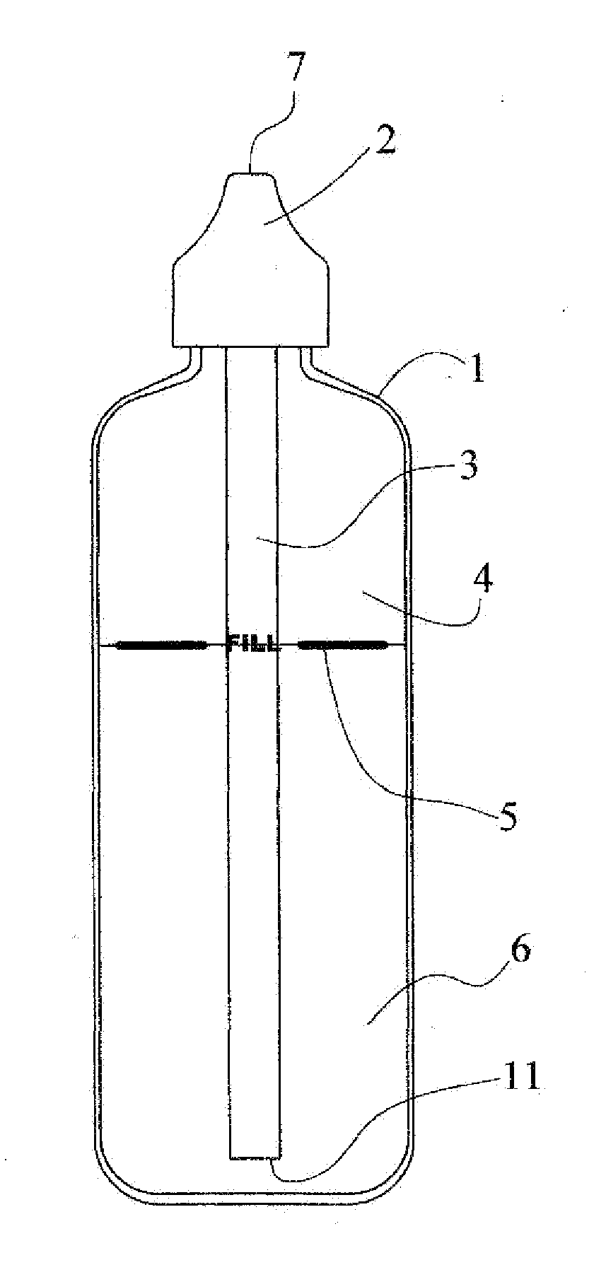
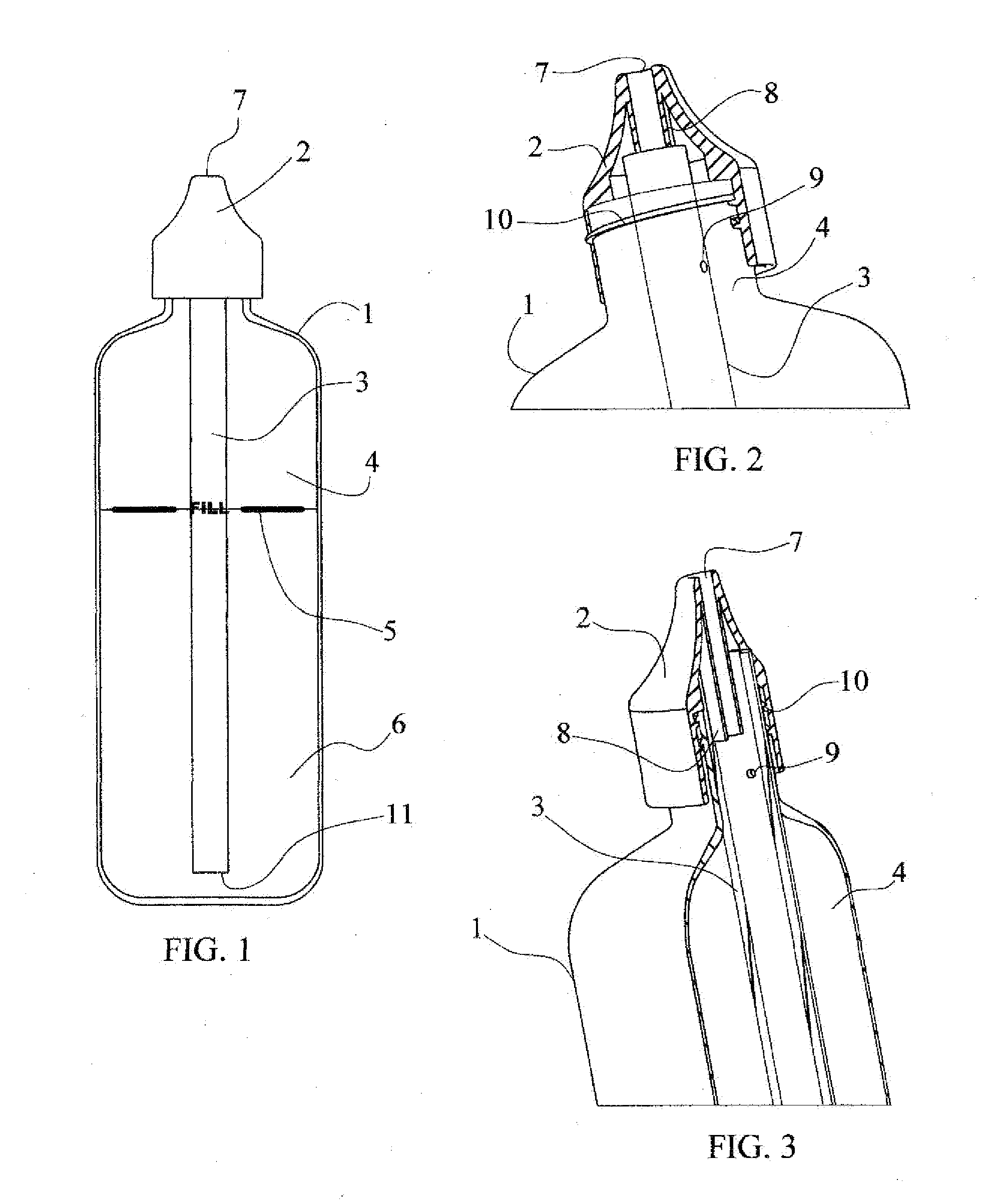
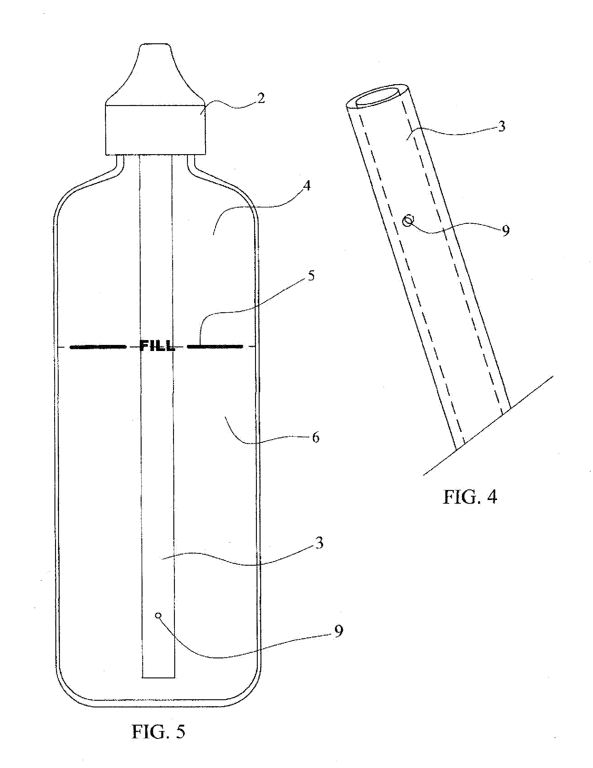
[0028]The term ‘confluence’ used throughout the present disclosure refers to a point of juncture of fluid in the fluid conduit or dip tube with air passing therein via an air metering orifice. An air metering orifice refers to an opening of a predefined area in the fluid conduit or dip tube wall, which passes a predetermined air volume into the interior thereof, creating air pockets in the fluid. The term ‘nipple orif...


PUM


Abstract

A high flow volume nasal irrigation device includes a squeeze bottle, a reservoir of liquid and a volume of air. The bottle is configured to elastically deform in response to a manual pressure from a user and thus pressurize the liquid and air. The device also includes a dip tube configured to convey a pressurized liquid flow from a first end inside the bottle to a second outside end at a lower pressure. A removable nipple cap comprises an orifice and a coaxially aligned extension configured to seal with the dip tube and to form a conduit with the tube. At least one air metering orifice is formed in the fluid conduit accessible to the to volume of air. The air metering orifice is configured to introduce a plurality of air pockets from the air volume into the liquid flow and thus generate a pulsatile fluid flow in the conduit.

Description

CROSS-REFERENCE TO RELATED APPLICATION[0001]This application is a continuation-in-part of and claims the benefit of the priority date of earlier filed U.S. Non-Provisional patent application Ser. No. 12 / 900792, filed Oct. 8, 2010 for Mark Carpenter which itself claims priority to U.S. Provisional Patent Application Ser. No. 61 / 278,455, filed Oct. 8, 2009 incorporated herein by reference in its entirety.BACKGROUND[0002]Flood irrigation differs significantly from the practice of inhaling an atomized mist into the nose. During flood irrigation, the vast majority (>95%) of fluid taken in is expelled immediately (or shortly thereafter) after the contaminants have been rinsed out. Rinsing with flood irrigation is commonly performed by ingesting the liquid solution into one nostril and concurrently expelling the solution from the other nostril. Alternately, flood irrigation is sometimes performed by ingesting the liquid solution into both nostrils simultaneously and having the excess fl...

Claims


Application Information

Patent Timeline
IPC IPC(8): A61M3/02
CPCA61M3/0262A61H35/04A61M2210/0618A61H2201/0153B05B11/043A61H2201/1253A61M3/0275A61M3/022A61M3/0208
Inventor CARPENTER, MARK
Owner CARPENTER MARK
Why Eureka
Try Eureka