Delivery Device For Medical Implant And Medical Procedure

a technology for medical implants and delivery devices, applied in medical science, prosthesis, computer-aided planning/modelling, etc., can solve the problems of unreachable devices from patients, limited anchoring depth of the anchor when released, and blood regurgitation during ventricular contractions, so as to prevent an undesired release of the annuloplasty implant. , the effect of avoiding undesired

Inactive Publication Date: 2014-06-19
AEEG
View PDF7 Cites 57 Cited by
  • Summary
  • Abstract
  • Description
  • Claims
  • Application Information

AI Technical Summary

Benefits of technology

[0067]Advantageously, the procedure includes restraining the annuloplasty implant in the hollow of the distal curvilinear shaped portion with a second restraining unit, and demounting the annuloplasty implant from the hollow upon releasing the second restraining unit, wherein the second restraining unit preferably is only demounted when a correct position of the annuloplasty implant is confirmed, allowing for removing the annuloplasty implant from the annulus if c

Problems solved by technology

One common example of valvular dysfunction occurs, when the annulus becomes excessively dilated or the valve geometry results in ineffective valve closure, which results in regurgitation.
Due to the increased diameter of the annulus, the leaflets or cusps fail to meet during systolic contraction, thereby resulting in the regurgitation of blood during ventricular contractions.
After deployment, the device is not retrievable from the patient other than by open chest surgery.
This may be a major disa

Method used


Image

  • Delivery Device For Medical Implant And Medical Procedure
  • Delivery Device For Medical Implant And Medical Procedure
  • Delivery Device For Medical Implant And Medical Procedure

Examples


Embodiment Construction

[0082]Specific embodiments of the invention now will be described with reference to the accompanying drawings. This invention may, however, be embodied in many different forms and should not be construed as limited to the embodiments set forth herein; rather, these embodiments are provided so that this disclosure will be thorough and complete, and will fully convey the scope of the invention to those skilled in the art. The terminology used in the detailed description of the embodiments illustrated in the accompanying drawings is not intended to be limiting of the invention. In the drawings, like numbers refer to like elements.

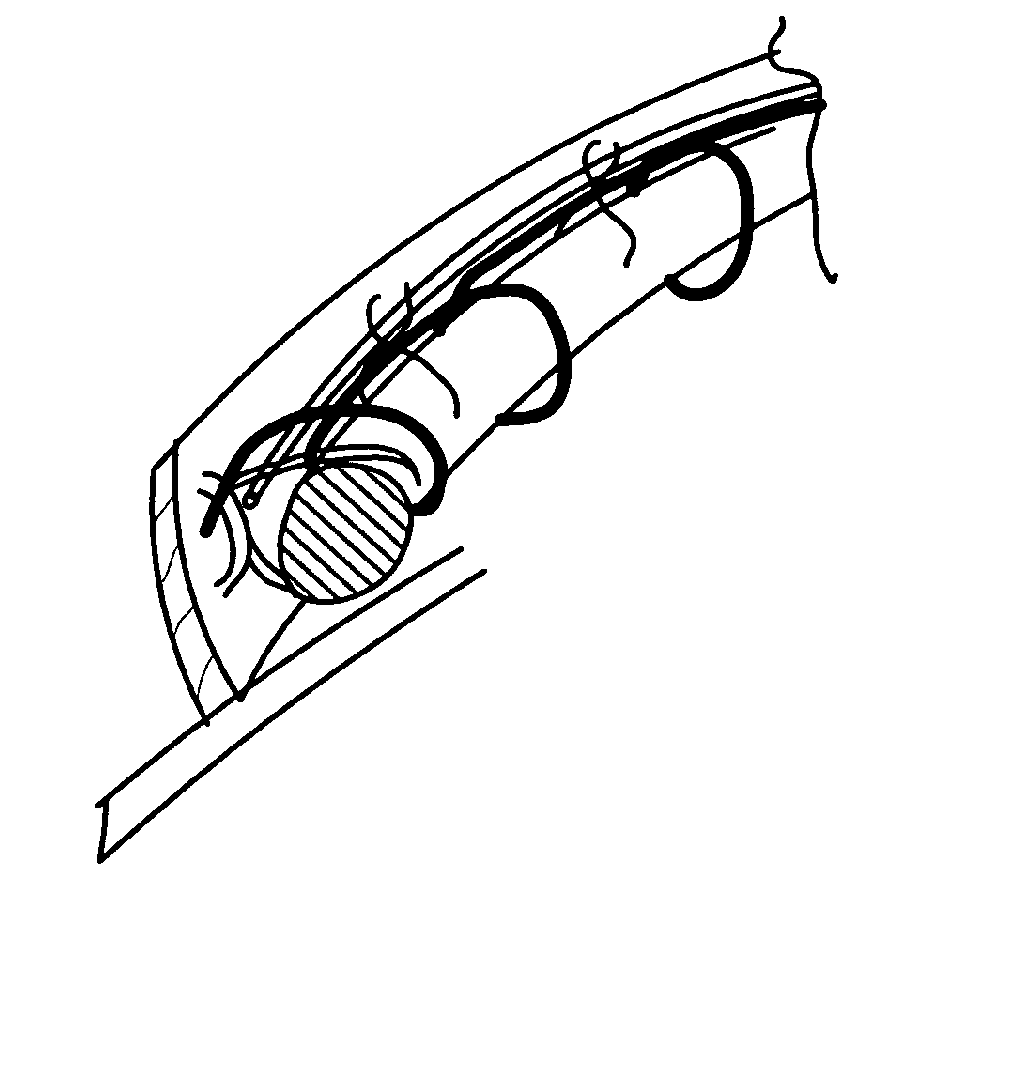
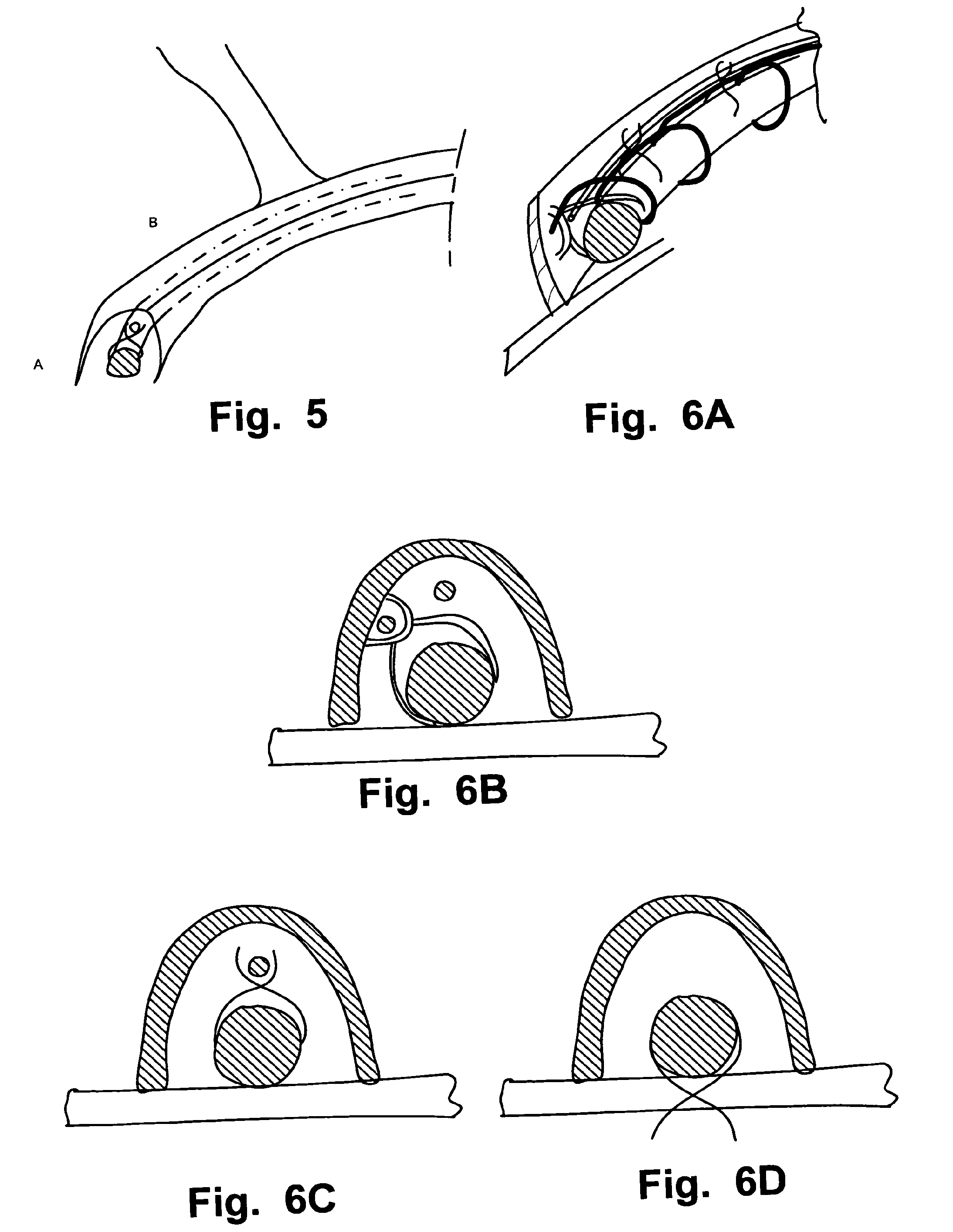
[0083]In an embodiment of the invention according to the Figures, a catheter 4 based medical system 1 for reducing cardiac valve regurgitation is shown. The system 1 has a resilient and / or elastic curvilinear shaped structure annuloplasty implant 3 for reducing the size of a dilated annulus 18 of the valve for reducing the regurgitation having resilient anchor...


PUM


Abstract

A catheter (4) based medical system (1) and medical procedure for reducing cardiac valve regurgitation are disclosed. The system comprises a resilient curvilinear shaped annuloplasty implant (3) for reducing the size of a dilated annulus (18) of said valve for reducing said regurgitation having resilient anchoring elements (300), and a delivery device (2) for said annuloplasty implant (3) having a distal curvilinear shaped portion (200) that is hollow to mount said annuloplasty implant (3) and has an annular opening (201) arranged to be in apposition against an annulus (18) of said cardiac valve. A plurality of suction units allows for a atrial approach and symmetric implantation of said implant.

Description

FIELD OF THE INVENTION[0001]This invention pertains in general to the field of medical devices and methods. More particularly the invention relates to cardiac valve repair devices and methods, and even more particularly to a system of cardiac valve annuloplasty implants and corresponding delivery tools for said implants, as well as associated methods and procedures.BACKGROUND OF THE INVENTION[0002]The human heart is a hollow muscular organ having four pumping chambers separated by four heart valves. The mitral and tricuspid valves, present at the left and right atrio-ventricular junctions, open and close in response to a pressure gradient during each cardiac cycle of relaxation and contraction to control the flow of blood to a particular region of the heart.[0003]These valves are comprised of a dense fibrous ring known as the annulus, leaflets or cusps attached to the annulus, and a complex of chordae tendinae and papillary muscles securing the leaflets. The size of the leaflets or ...

Claims


Application Information

Patent Timeline
IPC IPC(8): A61F2/24
CPCA61F2/2466A61B34/10A61B2034/104A61B2034/108A61F2/2445A61F2220/0008A61F2250/0096
Inventor JONSSON, ANDERSKRAHBICHLER, ERIK
Owner AEEG
Why Eureka
Try Eureka